This is just a quite short and incomplete article, compared to the previous ones.
On a rainy sunday afternoon I wondered if our audio receiver, a Kenwood KRF-V 7060, has some serial protocol which allows me to remote control the receiver via home assistant. I found some sources which explain the protocol quite well, also leading me to a github repository, which has the transmission part already implemented.
I wanted a bidirectional solution, knowing the current state of the receiver and also sending commands to switch it on and off as well as setting the volume. So I ported the code for the ESP32 and packed it into the common source base I use for my sensors and actuators at home.
Then I first started sniffing, later implementing the transmit part.
The physical layer
There are two variants, XS8 which transmits 8 bit commands and SL16 which uses 16 bit commands. As my Receiver uses SL16 only, I will mainly focus on this protocol variant here. The source should support both protocols, but has to be selected programmatically.
From what I’ve understood the protocol is using two 5V communication lines, one called BUSY and the other called DATA.
This bus seems to be a multi-master bus, any participant seems to be able to initiate a transmission. Whenever a participant wants to start a transmission, it raises the BUSY line to 5V while keeping DATA low. Then a start and data bits will follow.
All of the bits start with a low (0V) period and finish with a high (5V) period. The start bit for SL16 has both low and high periods 5 ms each. Data bits have 2.5 ms high phase in common, but the preceding low phase is either 5 ms for 0-bits or 2.5 ms for 1-bits.
Well. One source says so. The other one says vice versa and 1’s and 0’s are swapped. Also the endianess is MSB in the referenced github code.
However seeing the sniffed command of remote controls in this thread, it looks like data is sent LSB. You can’t easily detect this, as there is no reference what must be zero or other specific values.
After the 16th bit, the BUSY and DATA lines go low again and the transmission is finished.
In the linked github repository there are good logic analyzer and scope views for both XS8 and SL16.
The protocol
Well, there is no apparent protocol. It’s just 16 bits. A command ID. Maybe grouped into two bytes.
I will have to investigate this a bit more. Powering on and off got me e.g. EF7F which looks a bit odd for such a basic command.
Wouldn’t be surprised, if it is really 1080 as stated in this post. But when switching on is 1000 then, I would personally assume a different bit order.
So that we receive two bytes instead of a 16 bit word. Instead of 1080, I’d assume it was 08 01 and 1000 would mean 08 00.
This means the first LSB received byte is some command group and the next byte is the command. LSB of course.
This way the number inputs from the thread I linked would look like this:
05 01: 0   -> A0 80
05 81: 1   -> A0 81
05 41: 2   -> A0 82
05 C1: 3   -> A0 83
05 21: 4   -> A0 84
05 A1: 5   -> A0 85
05 61: 6   -> A0 86
05 E1: 7   -> A0 87
05 11: 8   -> A0 81
05 91: 9   -> A0 89
05 B0: +10 -> A0 0D
This also looks more “expected” to me.
Issues
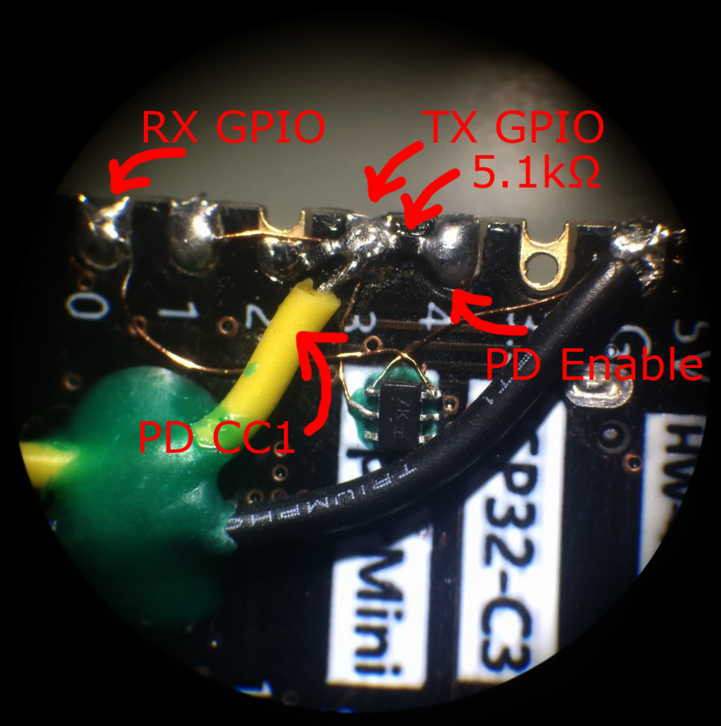
One thing that I have not mentioned yet – the ESP32 has 3.3 V GPIOs. Sending and receiving the data on the bus is not that simple.
Receiving only is simple enough – just use a resistor to limit the current over the protection diode, sinking the higher voltage into the 3.3V rail.
Sending only would work when using 5 V pull ups and using the GPIOs in open drain mode. Adding a resistor lowers the current over the protection diode and gets us closer to 5 V, but not exactly there. I measured approximately 4.3 V when the open collector IOs were open.
Unfortunately neither using 3.3 V mode, nor with these pull ups, the receiver did not respond to any of my commands.
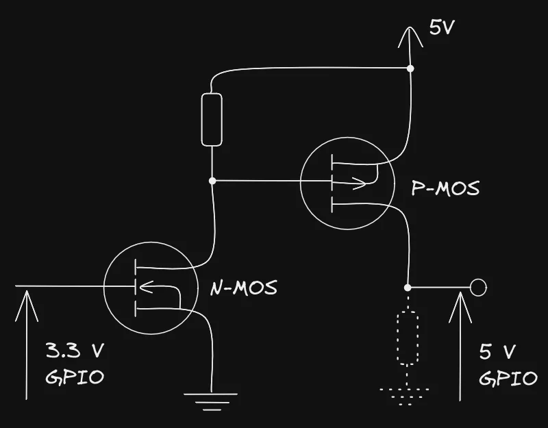
Being able to receive and send simultaneously would require a level shifter or an equivalent circuit. Toggling the pull up via 3.3 V GPIOs isn’t that simple. To my understanding it would also work with a P-channel as high side switch, a pull of it’s gate to 5 V and a transistor (or N-channel MOSFET) being driven via the ESP32’s GPIOs which pulls the gate low, enabling the P-channel.
I would drive the 5 V pull up with this circuit, by using another GPIO as ENABLE pin.
For now I stopped here.
Source code
You can find my current source here: https://github.com/g3gg0/ESP32_KenwoodRemote
Related Posts
[ESP32-PD] USB PD using ESP32 / Zigbee Crib
Emporia Vue 2 Custom Firmware