Imagine your child has a toniebox and they are very happy with it. You see them dancing to the music all day. That’s great, right? But sometimes you wish the box could work with headphones.
Oh, it does? That’s cool!

But wait, is this a wired headphone? How would your child dance with that 3.5mm jack cable connected to the box?
Nah, there must be a better solution.
Unfortunately, there isn’t one available yet. The toniebox doesn’t have native Bluetooth support (at least not yet). It’s a shame because I wish my daughter could wear her cute, brand new unicorn headphones with blinking LEDs she received on xmas everywhere in the house.

So, it’s time to add support for wireless Bluetooth headsets.
Opt for a DIY solution using ESP32?
I considered adding an ESP32 that would be wired to the I²S audio interface, capturing the audio signal for the DAC and transmitting it to the headset. There is already a library available that looks quite good. It’s called ESP32-A2DP and it can be found at https://github.com/pschatzmann/ESP32-A2DP. It features all use cases, except being an I²S slave, but it can be an A2DP master. After thinking about it, I realized that this would be a time-consuming project.
Off-the-self solution
So, I looked for an off-the-shelf solution on AliExpress and found a promising Bluetooth emitter called the “KCX_BT_EMITTER” version 1.7. It also has a LINK output.
I knew that the toniebox runs on 4.5V NiMH batteries, but the battery voltage is a bit low. Testing the module showed that it can even run down to 3.3V, but it won’t start up with that voltage. It requires 5V. Checking the toniebox PCB, I saw that there was a 5V step-up that powers the NFC section. Finally, I found all the required signals close to each other, except for the required 5V, which was a bit farther away.
Here is an overview of the vias that we have to solder the module to.
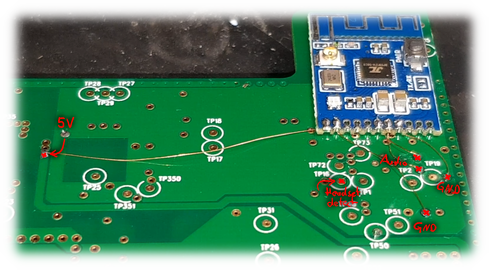
Here how to connect the module:
| BT Module | Toniebox |
| +5V | 5V line NFC section a bit left of the center |
| PGND | Ground-via in the audio section – separate wire and pad from AGND to reduce noise |
| LINK | (optional) Feeding into the gate of a MOSFET which pulls MICDETECT (“Headset detect” above) to GND |
| AUDIO_L | Audio signal – via next to TP2 and TP 19 |
| AUDIO_R | Audio signal – via next to TP2 and TP 19 |
| AGND | Ground-via next to TP2 and TP 19 – separate wire and pad from PGND to reduce noise |
Headset detection
This part is optional. If you already struggle with the thin enamel wires and don’t want to add this SMD part, just cut a 3.5 mm jack cable, put a 1 k? resistor between tip and GND and make it a mechanical switch by plugging it into the 3.5 mm connector.
When the headset is connected, the LINK output of the BT module becomes high, which then causes the MOSFET to switch on and drive the MICDETECT pin low. This causes the toniebox to switch to headset mode, which disables the speaker and saves the volume specifically for the headset. Any signal N-Channel MOSFET that works with 3.3V can be used for this purpose. One option is a Vishay Si2302 with a 0.8V threshold voltage in a SOT-23 package.
Basically you can use any N-Channel signal MOSFET, which works with 3.3V. I used a (clone) with 0.8V threshold voltage.
There are many sources like LCSC, ebay or amazon where you could buy such a MOSFET. They are very cheap.
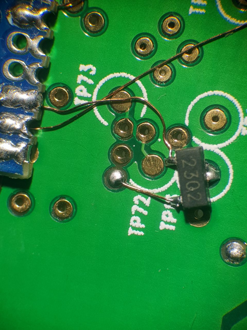
If you are not using an microscope, better place the transistor a few mm apart and connect it with short wires.
Toniebox hardware variants
Having a very early revision, I can only tell how well it worked for my version. However there are multiple hardware variants out there.
All have the same via layout and the soldering process is the same for all.
Unfortunately one very recent version has the vias covered with silkscreen, which you would have to scratch away using a sharp knife or a fiber pen.
Do this on your own risk.
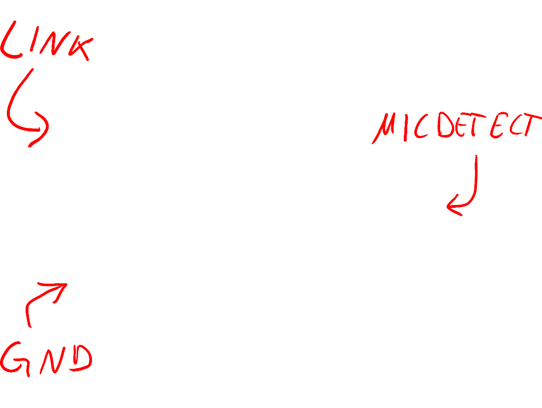
Black = GND, Red = +5V, Cyan = Audio, Pink = HEADDET
The Result
The BT Transmitter automatically searches for an audio sink which is ready to bind and binds with it. Once bound, it will always look for this exact device and will try to connect if it is available. Never tried, but when you press the button on that mini PCB, it will bind again to the next free audio sink. You might want to use that if your headset was replaced.
I’ve had this running for a day now and my daughter is happy with it. It seems to work flawlessly, with no hiccups or “meeh..” moments. The toniebox feels like it had this feature from the beginning. Here is a video of how it works, along with a few details on how I soldered the module.
Next steps
Some way to disable the LEDs of her headset remotely ;)
Update (24.04.2024)
Meanwhile a user named Paul on our RevvoX Discourse mentioned that the stability can be improved, if you solder a 10k? pull-down resistor between LINK and GND. This helps with some boxes, incorrectly detecting a headphone while starting up. If you face problems, give it a try!
Thanks, Paul!
Related Posts
[ESP32] Browser-based firmware image viewer and editor
Dyson v15 Battery Notes
One Comment