Since we own our house with a pellet heating system, it does its job day for day and delivers the warmth you’d expect from it. It rarely fails. Well, rarely. Except when I forget to refill the pellet container which has to be done every 3 to 14 days, depending on the season. Modern Windhager devices may feature WiFi, but mine doesn’t.
Find out how to get the system online
Unfortunately the system is closed and does not offer a simple solution of getting it online to notify me about any interruption, be it a failing component or just a failing human pellet refill bot. I could just upgrade the system to some automatic feeding system, but it would neither be the cheapest solution nor easily installed. Also I am a bit lazy to do this.
That was the reason for me to look a bit deeper into its guts and what is happening in it and how I could get this thing tell me whats happening. The schematics that come with the system quickly revealed some kind of local bus called LON which later confirmed speaking LONTalk from the 90’s on a RS485 physical layer.
But the best about this, the system has three slots where you can insert so called “MES-modules”, like the UML C1 or others. And only two of those three slots were used in my installation – one for the warm tap water and the second one for underfloor heating.
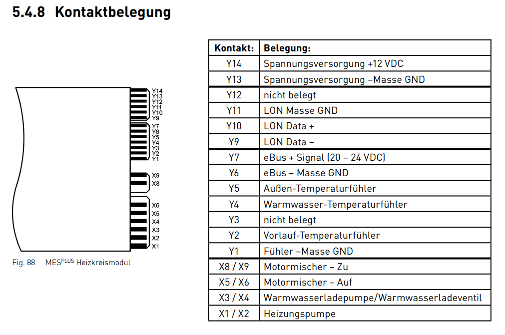
Not exactly my revision, but the important signals are the same. [Source, Pg. 48]
Analyzing the wire protocol
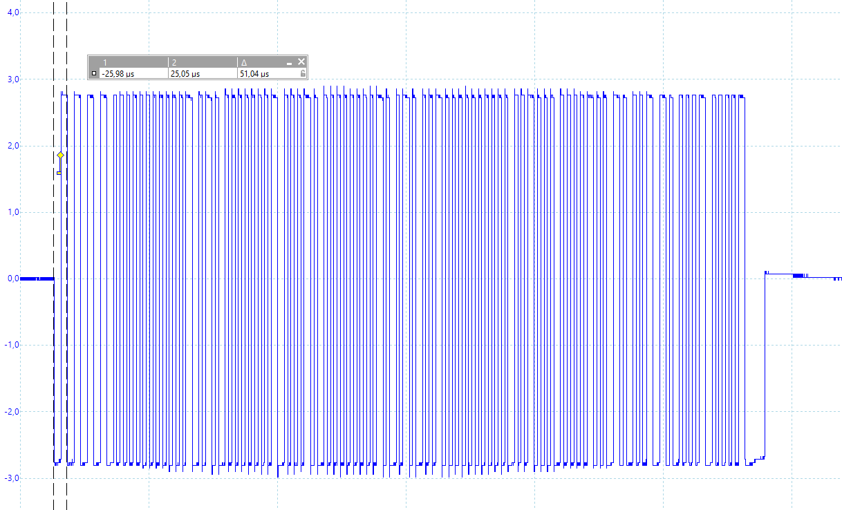
Measuring the physical signal confirms the guesswork and gives a signal with 78 kHz, which is biphase manchester coded and results in 38 kbit/s. There are usually 8 or 9 start bits (ones) and then the payload as specified in the LONTalk protocol specification.
While the specification defines all packet formats (APDU, TPDU, SPDU, NPDU, PPDU, …) addressing formats etc. this is not enough to get data out of the system. You have to know about the NV (Network Variable) IDs and their meaning, as well as the NM request codes to fetch certain values.
Thus I started with an ESP32 board, directly interfacing the LON bus and dumping all traffic via UDP to my LAN. Better than buying an off-the-shelf solution if you don’t know how far this project will get. Unfortunately was reading the signal not that straight-forward. While the transceiver is RS485, the encoding is not compatible to the RS485 standard. At least not to what I understand as “the standard”.
ESP32 implementation of LONTalk
So I had to implement the reading manually. After playing with bitbanging, I switched to interrupt based and ended up with the RMT hardware module, the ESP32 has.
No variant I have tried is really good. Bitbanging was obviously too CPU intense and I didn’t want to sacrifice a whole core for this. The interrupt based method had too much jitter depending on the WiFi state, and the RMT has also some downsides. While (IIRC) the TX path allows using multiple buffers and sending longer packets by somewhat using them in a circular way, the RX path only allows up to 8 buffers to be used. Minus one, because I use one for a WS2812. Also re-using already used RMT RX buffers is a bit weird and does not always work, so it struggles a bit in receiving longer packets.
However, the RMT engine seemed stable enough for my tasks, so I kept it and I am happy with it. On top of that, the important parts of the LONTalk protocol gets parsed and handled accordingly.
The first hardware revision
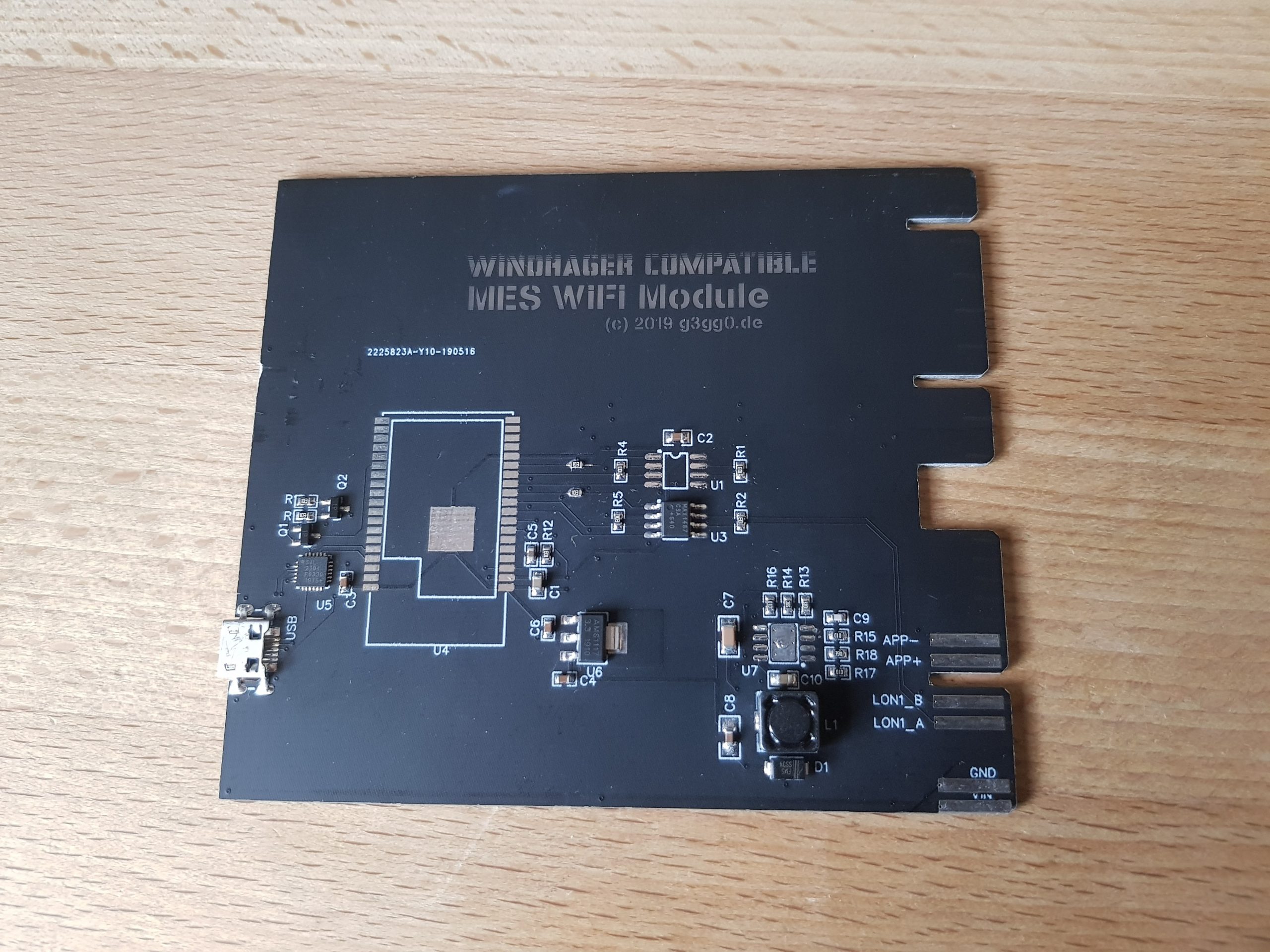
The MES-WiFi v1.0, equipped with a ESP32-WROVER module with PSRAM, was my first iteration along with a MP1584 for 5V and a AMS1117 for 3.3V. This was the first step to get things started, but not exactly the most efficient setup component-wise. USB and thus the CP2104 shall not be missed. For snooping the LON bus, a MAX1487 was chosen. My first revision had two of them, as I wanted to set up a test bench for stress testing the software by simultaneously forging and parsing packets.
It’s never finished at v1.0 anyway, so it was okay for me to start with a simpler, inefficient hardware solution. But these are the first steps to build my custom Windhager PMX150 WiFi
Analyzing the protocol
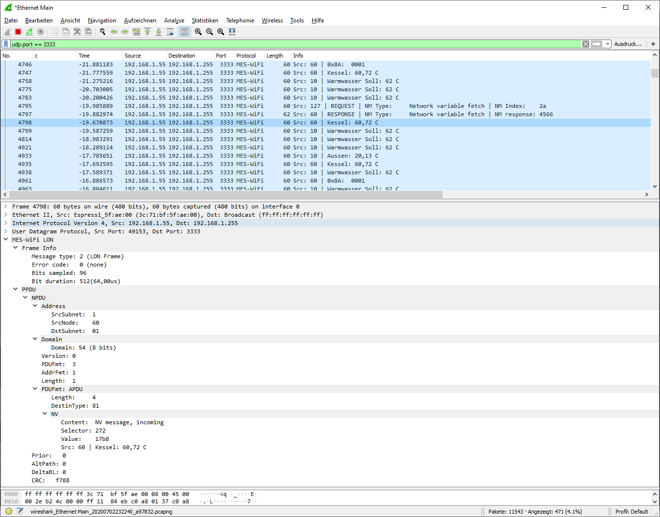
After the first revision was receiving the LON frames and UDP-broadcasted them into my WiFi network, it was time to analyze the content. Of course you do this tedious task with help of Wireshark. Step by step I built a LUA dissector that decoded the packets into readable form as shown below. A helpful person from mikrocontroller.net gave me a lot of information about similar modules that was neccessary to find out the IDs on the system I had.
All the packets get sent on UDP port 3333 to the network broadcast address (192.168.1.255 in my case). There is still a small header in front of the packet which decides between a “statistics” message and some real payload.
Sending data to port 3334 of the ESP sends the payload directly as a LON frame, without any header required.
Wireshark LUA dissector for LON: https://github.com/g3gg0/LonDissector
After the decoding was done far enough, the Arduino based ESP32 firmware was extended to not just “sniff” the broadcast messages seen above, but also actively ask some other Network Variables within the PMX main control unit and the other UML modules. You can see this REQUEST/RESPONSE pair in the screenshot above. All this information is not only sent as “raw” packets to my LAN, but also interpreted and fed to a really small MQTT broker on my server.
Warnings however, like low temperatures or an empty pellet reservoir, get pushed to my phone using pushingbox.
You can find my firmware on github.
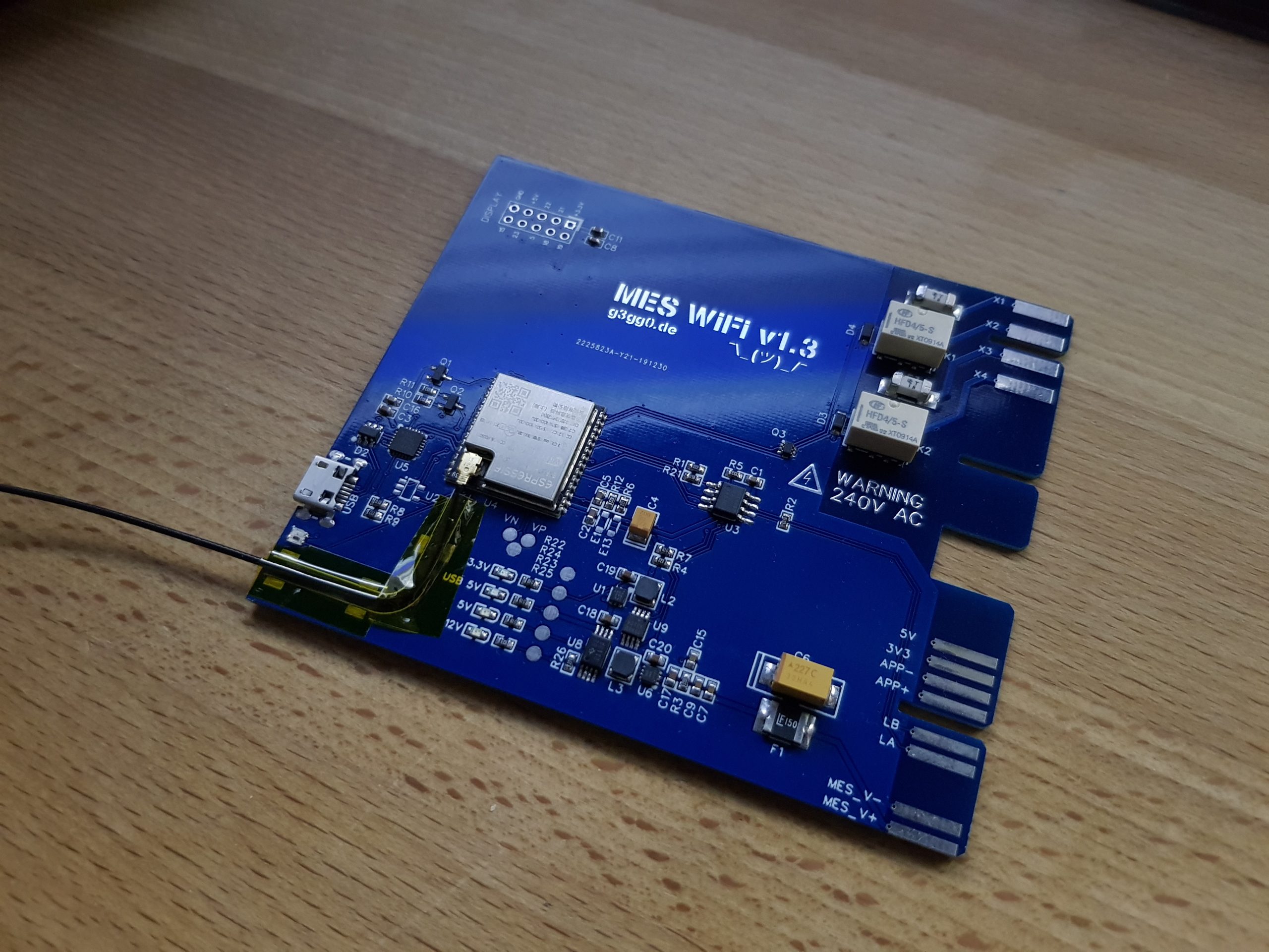
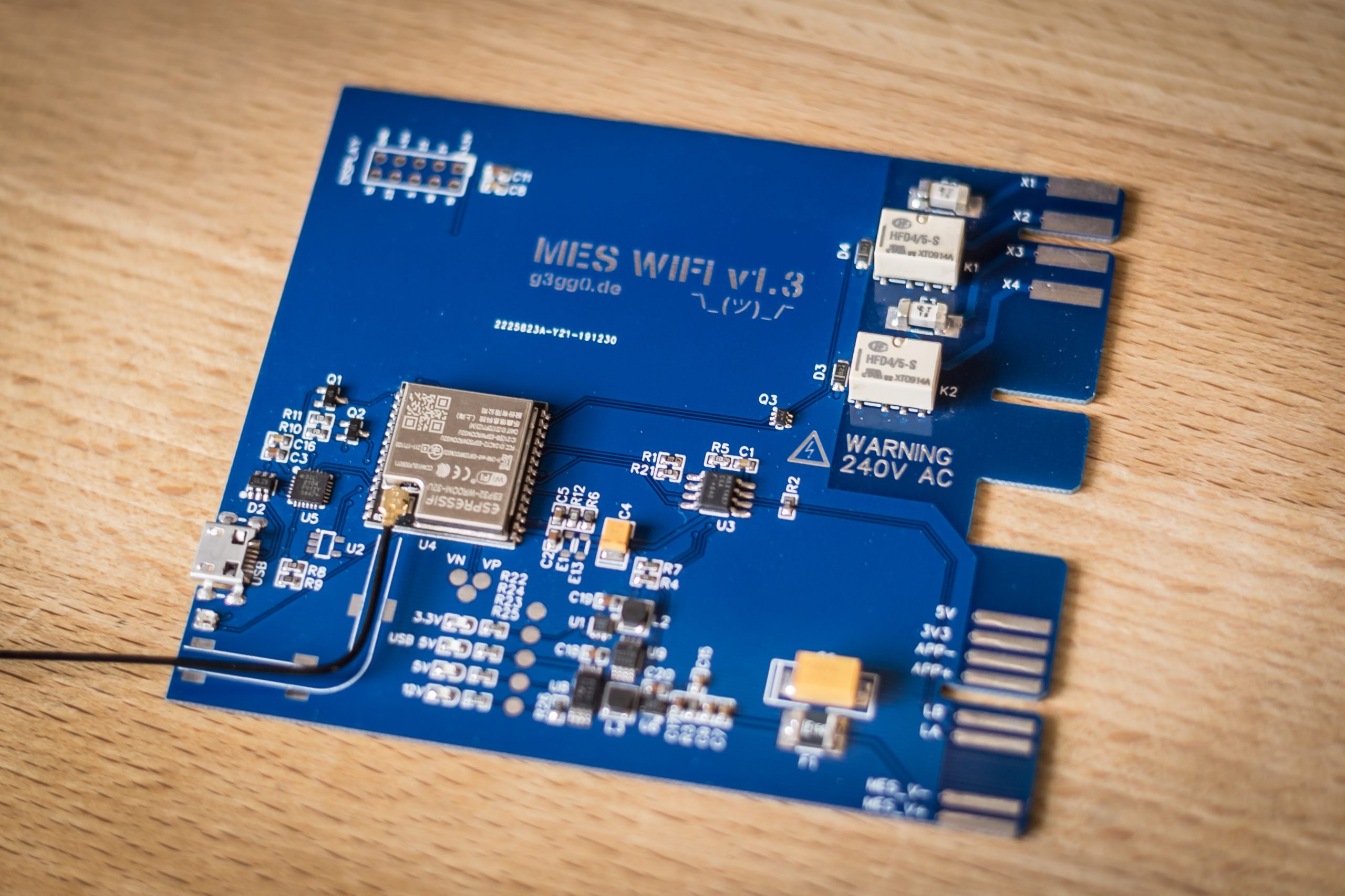
Hardware optimizations
When cleaning up the PCB – which is now at revision v1.3 – I changed quite a few things. Instead of the large WROVER module, I used the smaller WROOM without the PSRAM that I never used anyway. Also the inefficient MP1584/AMS1117 pair was replaced with TPS62163/TPS62291. WSON soldering with mm-scale components, yeah! I also added some smaller relays to drive some circulation valves. Somewhen :)
Finally I routed some IOs to the APP+ and APP- lines where I will attach the already installed 1-Wire temperature sensors measuring pipe temperatures.
The revision v1.2 was running half a year without any interruption, so I am optimistic that the v1.3 will also do a great job.
You can get the schematics and the layout on EasyEDA.
EDIT: Uploaded it here.
There is also a 3D printable housing on OnShape for the module, which reveals that I also planned to add an ePaper display, but did not find enough time to continue working on that.
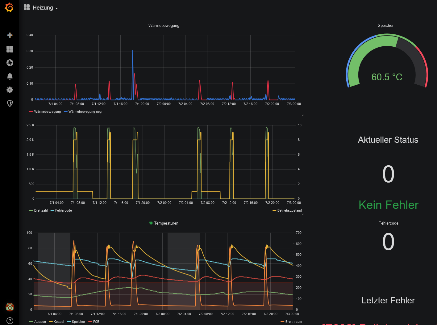
Visualizing data with MQTT, InfluxDB and Grafana
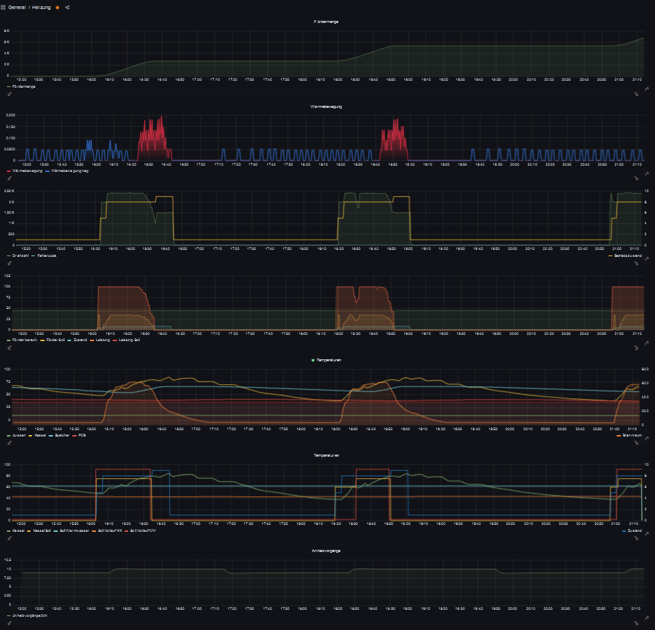
I am no specialist in this field, so forgive me that I don’t present a guide here. This is just image candy to show you how I set up my solution.
And here all graphical plots in a zoomed-out view.
Btw – I really love how the JLCPCB blue looks like. I can absolutely recommend it.
The red is also nice, but it misses a bit of this professional touch. If you are one of the brave ones, choose the black. You will never be able to trace your … uh … traces beneath this matte black finish.
Conclusion
So this was the journey of building a 25€ cheap WiFi extension module for a windhager pellet heating system, just by investing several dozens of working hours.
I really enjoyed reverse engineering the protocol on the wire level and implementing the code on an ESP32. What I enjoyed even more, was creating a PCB using EasyEDA and soldering it by hand. While I have a mini reflow plate, I still love manual soldering. Working hours with he colphonium and the Amtech tacky flux smell are just amazing.
Related Posts
Dyson v15 Battery Notes

ISO15693 Block for AARONIA RTSA-Suite