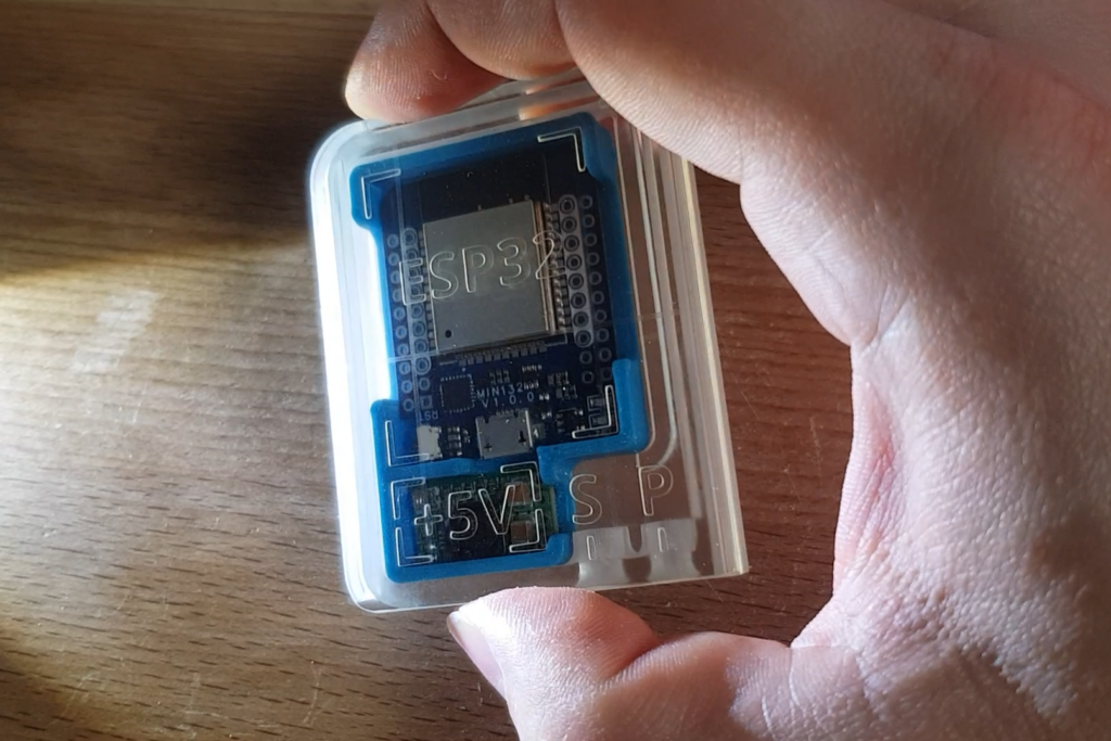
I am currently thinking about adding a laser to our Ultimaker 2 at work. Primary use case would be exposing PCBs to etch them on our own.
For this task we need some UV laser on the printhead. Well the chinese sellers on aliexpress.com sell them for less than 2€ including P&P, why not use them?
So i disassembled a standard 405nm blue-ish purple laser i had lying around and checked what is in there.
Ideal would be if these cheap laser pointers had a 24V capable constant current driver that allows PWM dimming using the UM2’s cooling fan output. Yeah that would be a bit too much to expect, but we are not far away. In mine I found a SOT-23-6 with marking “AN=P1U” which seems to be a Richtec RT8285B. The website tells me that the marking should be “AN-P1U” and not “AN=P1U”. But the circuit fits just well.
Here the hand-drawn “DaveCAD” compatible circuit.
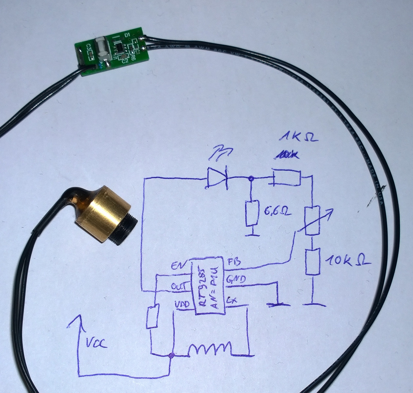
As i didn’t unsolder the trimmable resistor, i couldn’t measure its resistance. This would be needed to really know the max current etc. Edit: It was trimmed to 400 Ohm and its total resistance was 4.7 kOhm or 47 kOhm, don’t exactly remember.
But it’s already enough to build what we need. The datasheet explains that the EN pin of the B-version, which is thankfully active high, allows to dim the current by applying a PWM. Yay.
So just add a 56kOhm / 10kOhm voltage divider to get from 24V PWM to <5V and we can use the UM2’s fan speed control to dim the laser power.
Just the supply voltage with 5V maximum rating needs some extra circuitry. Perhaps its a good idea to low-pass filter the PWM signal, buffer it with a capacitor and use some cheap step down (like the LM2596) to get a good 5V supply.
But for the first tries, 3V batteries will to their job ;)
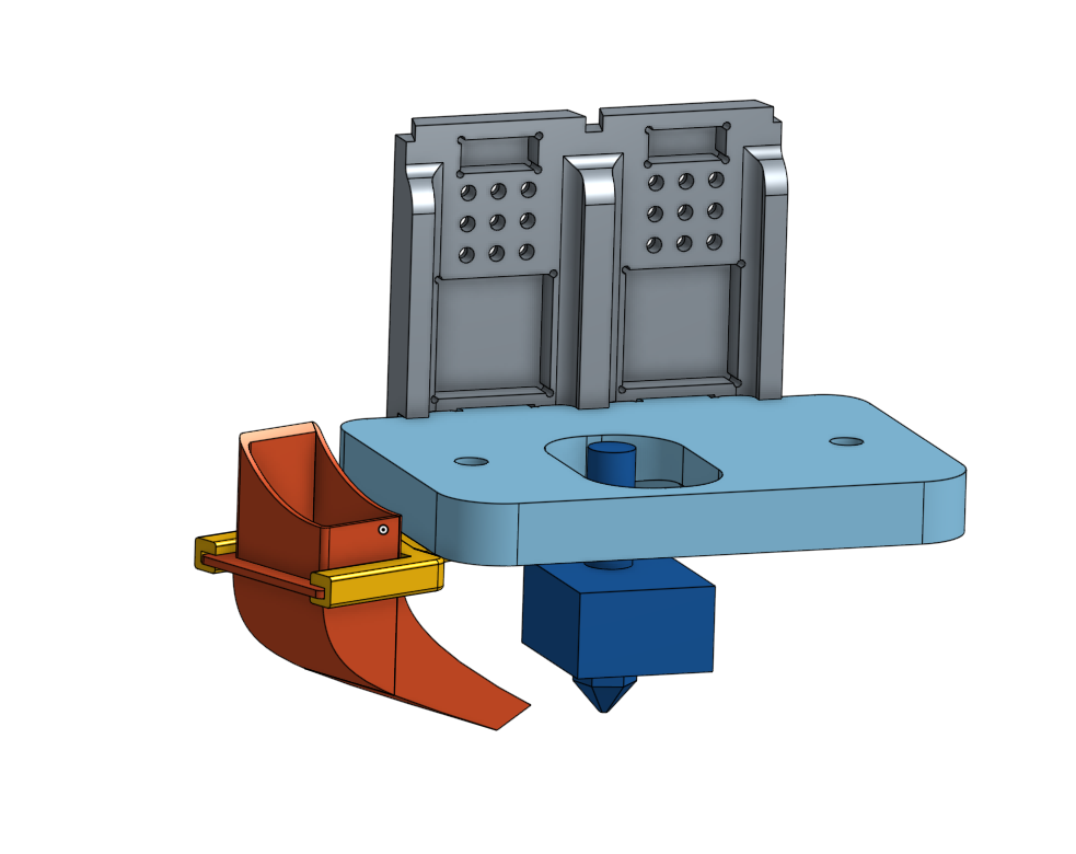
This is where I plan to put the laser (yellow). The UM2 guys initially wanted to add dual extrusion support, dropped that idea afterwards due to temperature issues that were to expect. So let’s use that hole for our plans.
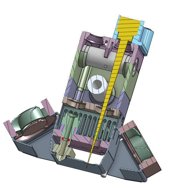
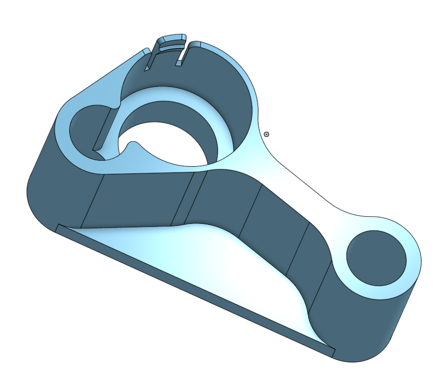
I designed that mount using OnShape, a free-for-makers online CAD tool which is absolutely easy to use by the way. I am going to print it that week and test a bit. Idea is to place the laser above the hotend area where it will – surprise – get hot during normal prints. So the diode can be left mounted during prints – or unmounted with the ease of just unplugging the adapter (light blue).
Then only the software thing is remaining. I am wondering if i should create a 1-layer 3D object from the PCB and let a slicer like cura do its job. After the slicer router the “ideal” print head movement, post process the g-code to disable material feeding and insert fan speed commands that corellate to the feeder speed.
Or should i just export the PCB into a bitmap(BMP/PNG/…) and code a custom tool that read the bitmap, raster-scans it and creates g-code from it.
Of course it should be intelligent to follow the paths with “laser on” pixels first until it cannot go further anymore, turn off laser and move to the next position where we need to expose and do the same here. This looks necessary to me because i don’t know how long the PWM stuff will take until the laser reaches the desired power. For fast head movements and thin lines i am sure miliseconds will matter.
It wouldn’t be as intelligent as a slicer that knows outlines and will draw continuous lines and uses zig-zag for infill. But it allows us to generate g-code from just a bitmap and gives us fine grained control over things like z position etc. Just imagine we could shift the z-offset to draw thicker lines ;)
We will see how far this will get.
Related Posts
Fuel Pressure Gauge for an Oldtimer
[3D-Print] Geeetech prusa i3 – improvements