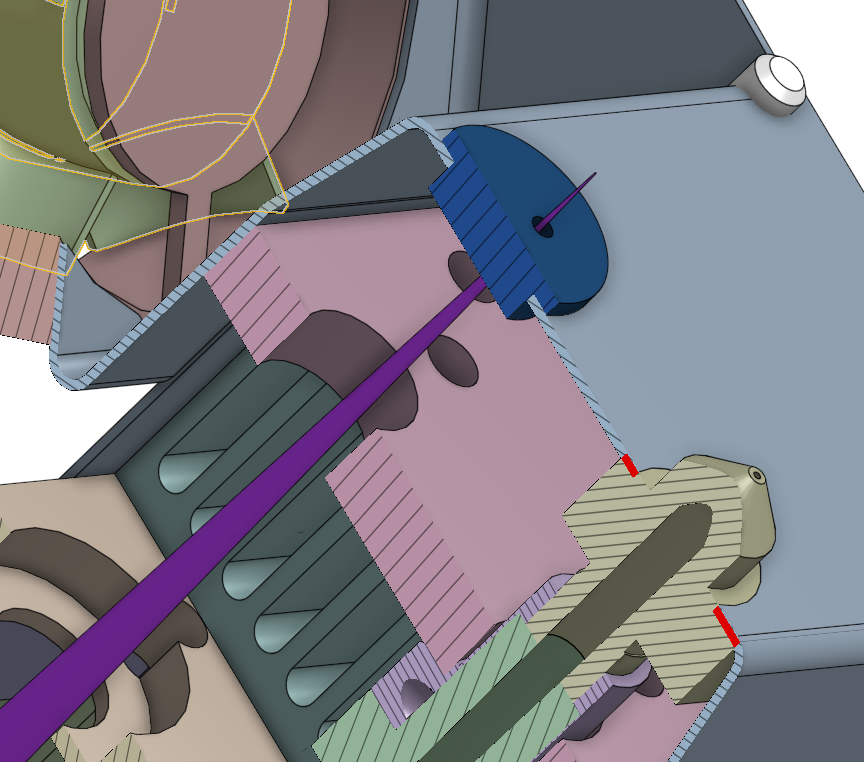
As previously described, I made a simple adapter to mount a 405nm blue laser diode to expose PCBs. There are for sure other methods that seem simpler, like separating the laser toner from a print or printing on transparent film, but our goal was to make it a “just press start” method using things we had lying around. No “process” that may vary with laser toner properties, chemicals, time involved. Just place it in printer and get a perfectly exposed PCB. Hopefully.
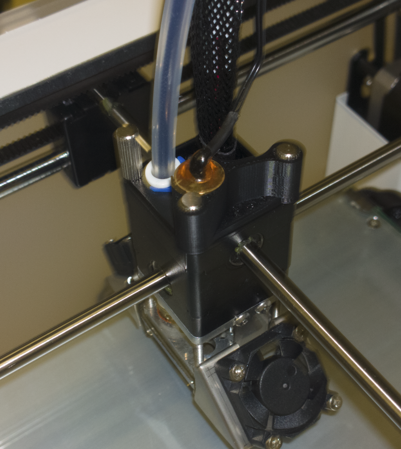
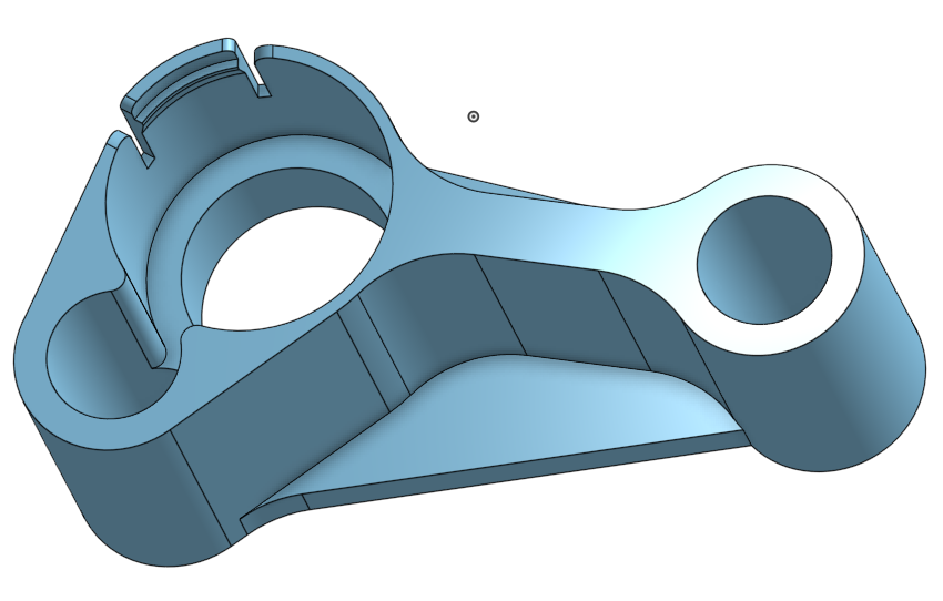
The first print of the laser mount was quite usable as you can see. Just the image is a bit blurry. Module sits tight, mount sits tight, looks proper. Just the “fixation” tab you can see on the 3D sketch was a bit clumsy and I just broke it off.
I searched for some EAGLE script that will output already usable G-code and was successful with PCB-GCODE. Some minor modifications were to do, then it was able to output G-code that switches the fan output whenever a line was to draw and so switch the laser on when exposing and off when moving across the PCB.
Some very careful tests of that G-code later, it showed that all is doing well. I set up the code to just home the Z axis and use the X/Y positions of the current head position as zero. This allows me to move the head manually to the board’s origin before starting, as I just fixate it with scotch tape for now. Played a bit to find the right Z position where the focus of the lens is best. In my case 12.5 mm above the glass plate. Just wrote that into the PCB-GCODE setup dialog, added PCB thickness and ready was the first G-code we ran on a real photosensitive PCB.
After exposing the first PCB, my colleague developed and etched it. The first try was a quite okay. A bit overexposed, but the technique seems to work. Fan output is driving the laser module’s enable pin correctly and it’s perfectly (over-)exposing areas.
This exposure was using 100mm/min at ~80mA laser power. Next time less current.
Also added an aperture plug to reduce the reflections the laser is causing in the metal on its way down. Now the spot is very clear and small, no scattered light. Just some reflections of the light coming back from the PCB, hitting the metal fan shroud and reflecting back to the PCB.
While experimenting with the laser output power, I used a Keithley SourceMeter 2400 for providing stable 3.0V. Using the Ultimaker 2 menu, I played with the fan speed. What I didn’t think of, was the dynamic behavior of both SourceMeter and the constant current driver of the laser module. A few “fan speed” sweeps up and down later, the laser started to blink and go off.
Shock. Did the laser module die? Power consumption went up from ~580mW to > 1W and the SourceMeter limited the current. A short test by driving the laser module directly, showed that the laser itself is still functional. Phew. So the constant current module died. I am quite sure that the (measured) 490Hz PWM of the UM2’s fan output caused the whole setup to oscillate and the RT8285B to catastrophically die.
Well, picked up a AQY221R2V solid state relay from our laboratory and used this to drive the laser module directly with the PWM output. For now I will not use the PWM to control its power, just use 0% and 100% :)
After doing some calculations, based on experiences of other people on the net, some estimations of the laser module’s power (using SLD3132VF as reference) I came to some approximated values of movement speed and laser current. Basically I am trying to get the same amount of energy to the ~50µm focused spot as some people who had success exposing with a 300W halogen lamp all at once. Interesting number: with the laser we have about 8 MW per m² energy concentration.
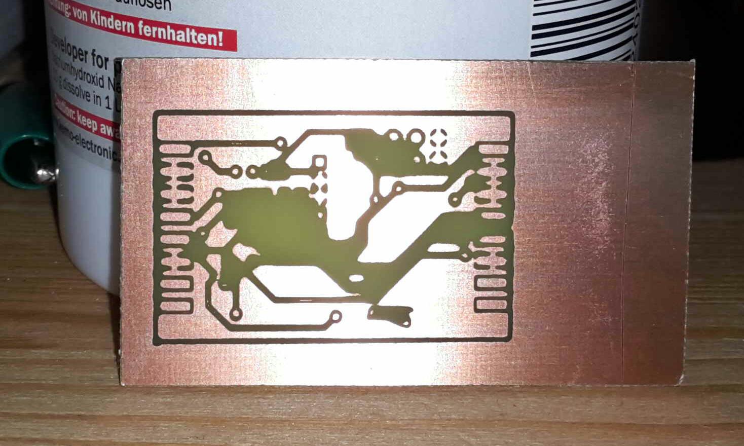
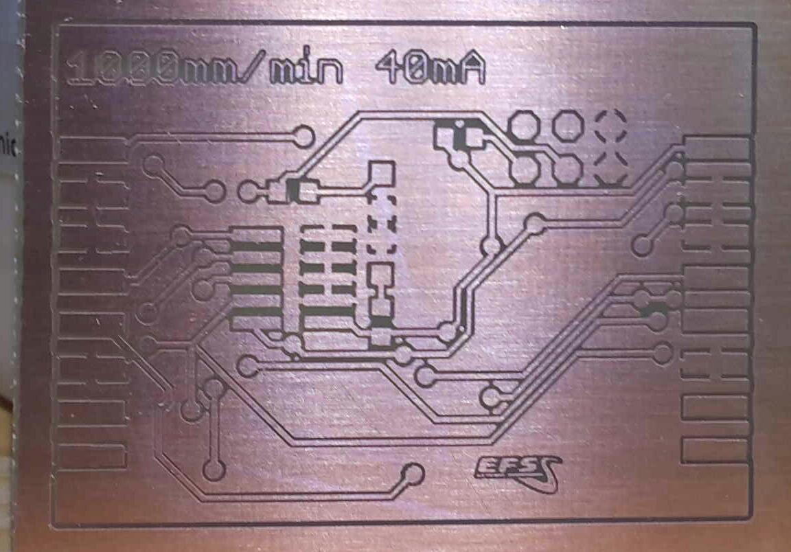
Here are the first tries with varying speed and current to find out where the sweet spot lies.
![AgWPXHE02gWpTg5D6A7M_Dp8pyW8RENd00XKU-koJuAf[1]](https://www.g3gg0.de/wp-content/uploads/2016/02/AgWPXHE02gWpTg5D6A7M_Dp8pyW8RENd00XKU-koJuAf1-optimized.jpg)
The result with 1000mm/min at 40mA laser current is really overwhelming for such a cheapo 2,50€ extra cost setup.
So this was quite successful. A bit more fine tuning to find where the limits are, e.g. the minimum laser current, the perfect focus plane level, the minimum line width and a bit of tool-tuning to get the drill holes laser-marked too. Then design and print some mounting frame to repeatedly hit the same zero offset when fixating PCBs and thus be able to expose two-sided PCBs.
The cool thing is – I just poweroff the laser and am able to print ABS just the minute after, without any de-/setup procedure.
Thanks to my colleague Franz for his support, especially for etching the PCBs.
Next stop: drilling ;)
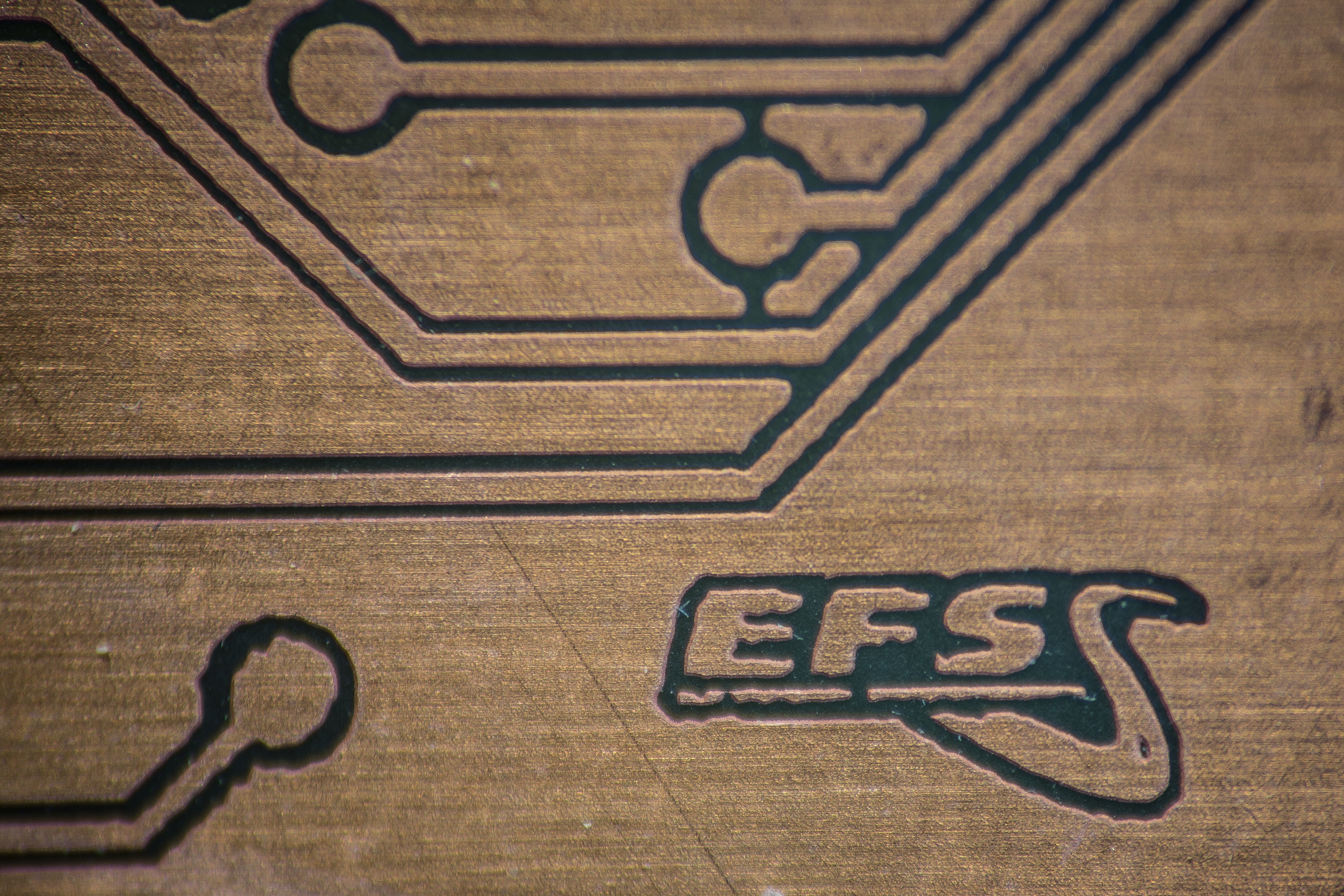
Update: And here a close-up zoom with a macro lens:
And currently i am uploading a video that shows the setup being in action with a dry-run on paper.
Related Posts

[ESP32] WebFlasher in ESP-IDF
[ESP32] WebSerial / WebUSB – another Rabbit Hole