Many years ago when I was young, I always wanted to have technic bricks to build some cool stuff with it. Self driving tanks, rotating cannons and shooting smaller bricks around. But back then I had no technic.
Well, not even bricks. Just a friend whose brother had this expensive stuff.
Now I have a son in this age and well… he builds tanks that… stupidly drive until they crash into a wall :)
Time for some ESP32 and soldering wizardry to build a proper REMOTE CONTROL!
No no, I know there are some remote controls around there. But none fits really well. Either 80’s infrared or bulky. Or too expensive.
And most important – none of them of which I can say to my son: “I built it for you!“
So lets build a new, better one to rule them all!

Ingredients:
- ESP32-WROOM-32D | WiFi, BLE and enough processing power and IOs to control two motors and a LED light
- DRV8833 | dual H-bridge for enough power to drive the motors
- TPS62162 | step down for up to 17V input voltage, and also for having fun soldering the 2×2 mm WSON-8 package
- CP2104 | just for programming the ESP32
- Power functions connectors to connect the motors and lights.
Will cut the wire and solder them to the bottom side and glue the brick/connector to the top side
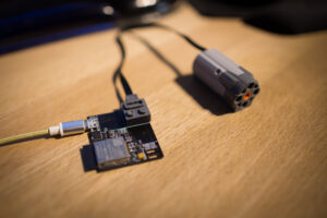
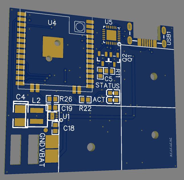
All this in a rather small footprint, here as shown in EasyEDAs 3D view:
The wire you can see on the PCB photo at the top of the article is not to patch some bug, but to feed the USBs 5V to the power supply. It will probably not be enough to power a motor, but unfortunately the connectors from china didn’t arrive yet. So I was testing with LEDs only in the first place. For the photo I just placed the motor connector losely onto the PCB without function.
To see what the motor driver does, the v1.1 had (unlike the v1.2 now on EasyEDA) no LEDs designed onto the PCB, so I soldered two antiparallel diodes to the outputs so I can see whats happening. If you look closely in the video you can see the two 0603 diode pairs alternating, which are indicating forward/backward motion.
For the control I first wanted to build an extra PCB with buttons and another ESP32, a classic remote control.
But I somewhen remembered that the Steam Controllers have a BLE mode. So sat down and a few hours later I was able to receive packets from the controller. Basically you just search for a HID device that announces as “SteamController” and connect to it. Then just use some undocumented Valve service and some undocumented command with it to enable packet transmission.

Then there was some also undocumented report format which I reverse engineered manually.
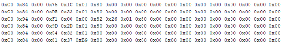
After a hour or so, all flags and values made sense and I was able to blink LEDs using a Steam controller and an ESP32. ¯\_(?)_/¯
I will upload the sources and update this post later.
Project files:
- Schematic/PCB: On EasyEDA https://easyeda.com/EFS-GH/legoremote
- Arduino sources: GitHub https://github.com/g3gg0/LegoRemote
v1.0: “first try”
– first revision, but had chosen the wrong voltage regulator. TPS62291 only goes up to 6V. had few projects in parallel and simply forgot that this device had to cope with 9V
v1.1: “good enough”
– the version you see in the videos with everything working fine
v1.2: “final”
– added indication LEDs to driver output and optimized layout and PCB size
Here a short video showing the connection phase (1-3 seconds after switching power on) and controlling the motor outputs. The LEGO connector for the headlight was not populated there. It will go to the empty space marked with the white rectangle right next to the other connectors.
Meanwhile my son uses this device on a regular basis to control his tank like constructions.
During his stress tests, I faced only one issue – the driving mode of the motor I expected to work best – fast decay – caused some serious speed drop after a few seconds of driving. So I changed to code to use the slow decay mode.
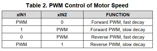
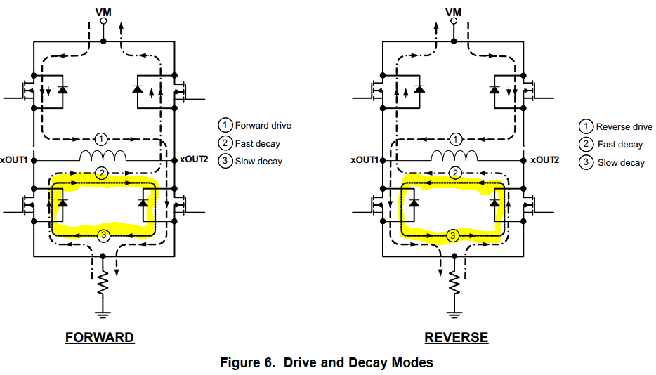
I will have to dig deeper into what the DRV8833 exactly does and try to understand why the motor first runs at high speed and gradually slows down after maybe 10 seconds. Maybe MOSFETs are heating up and their resistance is raising a bit too much. Not sure.
But for now this is bypassed by using slow decay.
Maybe this is some inspiration to other people what you can use your arduino playground for without too much effort and get your kids interested in electronics also.