I started flying FPV quads for a bit of freestyle flying about two years ago. Not very skilled, but also flying every now and then, so no real focused learning.
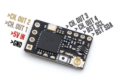
Quickly I jumped onto the TBS Crossfire train and bought a TBS Tango 2 and a few Nano RXs. I liked the compact design of the remote and the idea of having a flexible telemetry protocol. Of course I also looked into the Crossfire serial protocol (the one between quad and the receiver), but thats another story.
I am aware that there is now tracer and even an open source solution ExpressLRS which also features an ESP on the RX side, which is quite cool. Having extra wifi on the Rx is kinda overkill, but its for free.
Anyway. Soon I realized that the Crossfire Nano RX is basically a PIC32 and a SX1272 LoRa modem. So I found it very practical that there is an ESP32 based, easy to use LoRa device with display. The Heltec WiFi LoRa 32 (V2).

So what can we do with it? Can we sniff Crossfire? Can we Hijack it? Or can we do some DoS attacks?
Well, lets try to find out.
Fist of all we have to determine which features of the LoRa modem Crossfire devices are using and which frequencies are used. One possibility would be dumping the firmware and reverse engineer it as I usually prefer to do. Stumbling a bit around, I managed to get a list of their firmware versions and also some firmware file links available without any authentication. When looking closer at those files, the files seem to be encrypted.
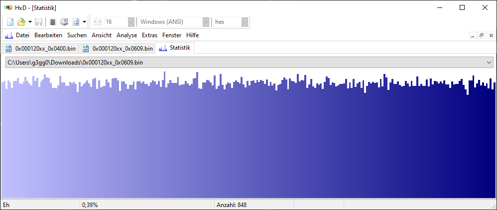
Comparing the binary files using a custom tool I made (think of it like an advanced hex editor), you can see that the encryption is probably a block cipher with 8 byte blocks, or maybe a simple XOR based encryption. It also looks like there is a 10 byte header that contains the hardware ID and firmware revision.
Well, I did break this kind of encryption a few years ago using known plaintext, but this took some time and I didn’t want to spend too much time on it. Spoiler: I still spent quite a lot time though…
So the encryption is spoiling the fun and no quick win there.
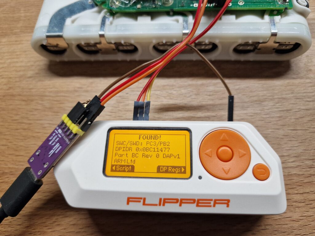
Now, shall we dump the firmware from the PIC32MX170F256D using some ChipWhisperer attacks?
Nah, my beloved IDA Pro Advanced doesn’t even support that chip, so it would probably be a bit too much work finding out the registers etc.
So I decided to sniff the SPI communication between the PIC32 and SX1272. Not having a logic analyzer here right now, but a few FPGA boards, the next steps were clear.
After a bit of soldering, I connected those lines (MOSI, MISO, SCLK, SS) to an CYC1000 board from trenz electronic – which I received from ARROW at an embedded world visit a few years back. Great hardware. Only a few bucks and you have a powerful FPGA board on your desk. Get one of those and play with it.
First I tried one of those readily available logic analyzer designs that work with sigrok PulseView, but that didn’t really work out. Just received a few bits and then silence. So I decided to design my own SPI sniffer.
Didn’t want to spend a lot of time, do you remember? ;)
After modeling the block schematic in Quartus and writing the SystemVerilog design of the SPI log engine, the hardware part was ready to go. Well, I hate clock domain crossing. Seriously. Especially when a dual-clocked FIFO of Intel’s IP library doesn’t solve the glitches.
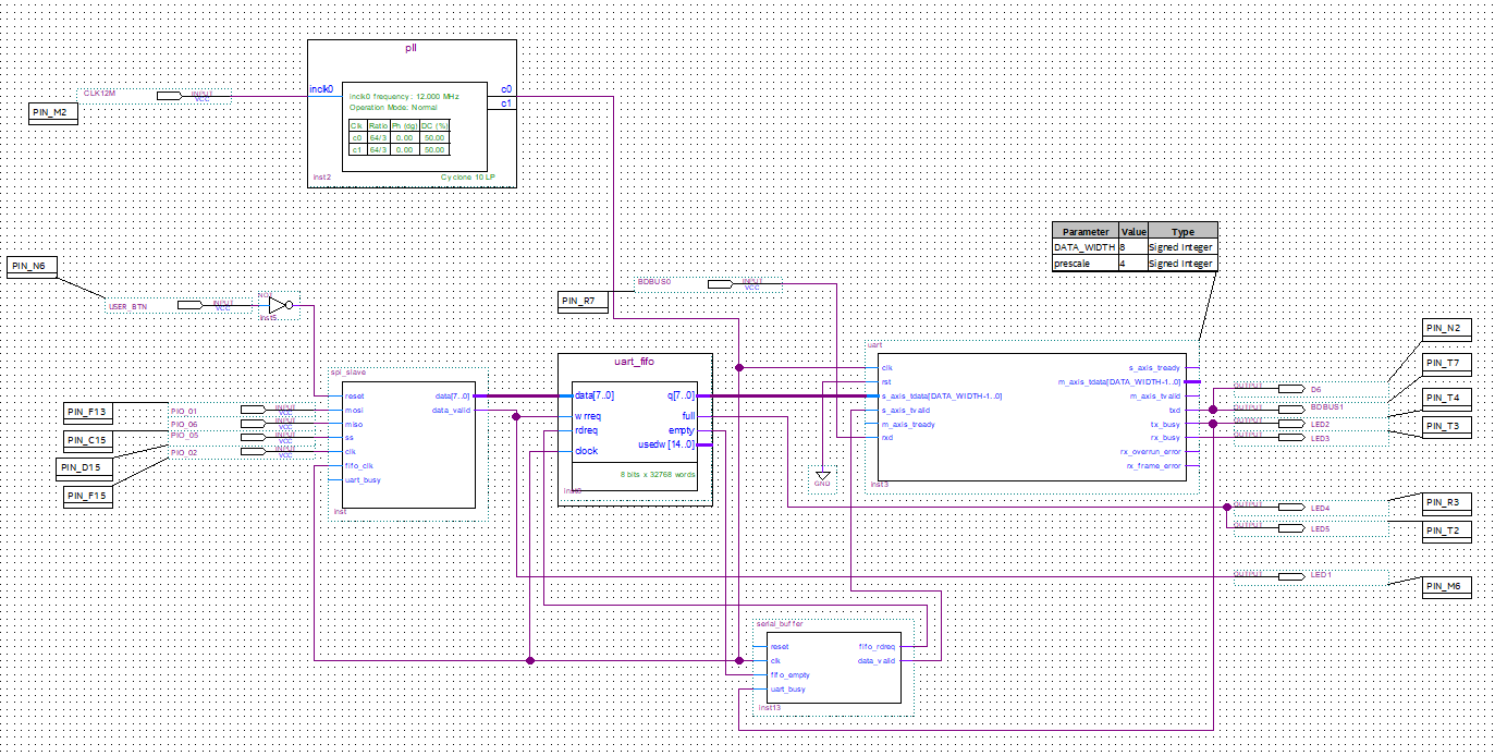
After a few additional hours of C# hacking, there was a SPI sniffer tool, that receives the data from the FPGA via USB serial port and parses the SX1272 register reads/writes to show a log of all configurations made. It allows saving the logged binary data and playing back the log, if I add a new parsing or analysis feature later.
It also logs the frequencies and builds a map in which order the channels are changed. This channel hopping sequence is most likely only valid for my configuration and my bind key – if something like that applies to Crossfire. For other TX/RX pairs I expect the channel sequence to differ.
Lets interrupt for a second and talk about some terminology
“channel” – the used frequencies are all equally spaced from each other, so I assume there is a logical channel numbering, being 0 the channel with the lowest frequency I have seen
“uplink” – data sent up to the quad by the TX / remote control
“downlink” – data received from the quad
On most modes, the Crossfire protocol uses channels 0-49 for TXing data to the receiver, then switches frequency exactly 50 channels up and the receiver answers on channels 50-99. Then the TX switches to the next channel according to the hopping sequence. This process is repeated 150 times and then the whole hopping sequence repeats.
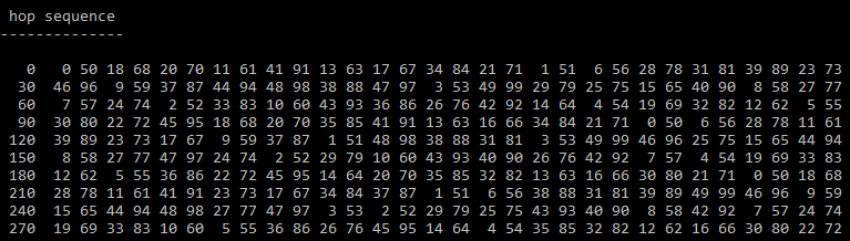
So in this example above, the TX sends its data on channel 0, switches to channel 50 and waits for the RX to acknowledge the data and send telemetry. Then the TX switches to channel 18, sends its uplink data and waits on channel 68 (18+50) for the RX to answer. After all channels in this sequence were sweeped, it starts over again at channel 0.
RACE modes however, stay on the same channel for uplink and downlink data – but use channels 0-99 for hopping.
The exact frequencies might also be part of the initial binding and so my theory might be wrong. Will test it on other setups too. All of this communication was done in the FSK mode of the LoRa modem, having a frequency shift of 42.48 kHz and a bitrate of 85.1 kBaud.
These are the frequencies my setup uses:
| 868 | 915 | 868 RACE | 915 RACE | 868 CE | 915 AU | ||
| Fmin [MHz] | 860.165 | 902.165 | 860.165 | 902.165 | 863.093 | 915.165 | |
| Fmax [MHz] | 885.905 | 927.905 | 885.905 | 927.905 | 868.581 | 927.905 | |
| Channels Rx/Tx or shared | 50/50 | 50/50 | 100 | 100 | 50 | 50 | |
| Spacing [kHz] | 260 | 260 | 260 | 260 | 112 | 260 | |
| FreqShift [kHz] | 42.48 | 42.48 | 42.48 | 42.48 | 42.48 | 42.48 | |
| Bitrate [kBaud] | 85.1 | 85.1 | 85.1 | 85.1 | 85.1 | 85.1 |
At this point in time, I started coding an arduino sketch for the Heltec board. I wanted to see the data being griefed out of the air instead from a lame SPI log. Also – although in this post it seems I was sniffing both directions of that SPI communication from the beginning, but in reality at this time I only sniffed the writes to the LoRa chips, committed by the PIC32. This was enough to get the settings, but misses what the Tango 2 TX sent. Only later the full SPI communication was logged.
Although having the hopping sequence, I started an arduino sketch that simply waits on a single channel for data. Hopping is something that can be added later, first configure the SX1276 of that Heltec board to receive data from the TX. Maybe you already noticed – SX1272 and SX1276. One of them is on the Nano RX and the other one on the Heltec board.
Luckily they are quite compatible, just a few registers are different. So no simple replay of the logged data, but code it all manually. Would have to do this anyway, so thats okay.
After a few hours I received the first data from the remote control. The payload (23 byte uplink, 13 byte downlink) was of unknown format, but quite obviously coded. Interesting is the fact that over the air only 10 bits of resolution is used whereas the serial protocol uses 11 bits. I don’t expect this a huge quality issue for Crossfire, but it was unexpected and caused some confusion to the least.
Some other interesting fact:
When you use the 8-channel mode, the TX sends sticks 0-7 on every packet.
If you use the 12-channel mode instead, then the TX sends sticks 0-3 on every packet and alternates sticks 4-7 and 8-11, dividing their update rate to the half.
The alternating packet is marked in the first byte of the uplink data (bit 5 set)
Regarding the timing, having a RX/TX pair every 6.666 ms is due to the 150 Hz rate quite expected. The downlink packet is received at latest 2.6 ms after the uplink packet has finished sending. This period is shorter as the downlink packet is a few bytes shorter. Will do some maths and build a schedule table if I get all numbers right.
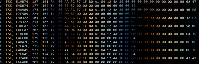
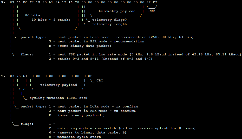
Also the CRC was obviously placed at the end of the packets, but the TX used 16 bit CRC in the uplink packets and the RX answered with 8 bit CRC in the downlink packet.
Unfortunately the CRC never matched and quickly I realized that there must be some seed that is used to initialize the CRC. Even packets with identical payload had, depending on the hop number, different CRCs. After a second, when the hopping sequence repeated, the init values also repeated and so the CRCs did. This means every of these 300 hops per second (150 up/downlink packets per second) must have its own init value for the CRC.
After I noticed that, brute forcing the exact CRC type was just a matter of a few hours of coding.
CRC8: poly 0x07, refin=false refout=false xorout=0x00
CRC16: poly 0x1021, refin=true refout=true xorout=0x0000
But the init value is unknown and depends on the hop number.
When doing a firmware upgrade or binding the receiver, this happens in LoRa mode and uses the CRC8 with init value of zero. Of course is the firmware data over air still encrypted and just the data we have seen above, right after the 10 byte header.
This CRC initialization with the hop number and some seed value is clearly a sign that TBS wanted to make sure multiple TXs in one area cannot interfer with each other in a way that incorrect stick values get interpreted by a RX that should not receive the data.
But is this some sort of security feature?
Definitely not. I can already detect the hopping sequence through listening and timing measurements and also capture the CRC init values from air without anyone noticing. Then I could use those values to fake a TX and gain control over a victim’s racing quad. Not done yet, but easily™ possible from what I know right now.
After struggling with timer issues in the arduino-esp32 library that seem to be a bug in the SDK, the exact timing to follow channel hopping was possible.
If you follow the hopping sequence correctly, you will log all stick values and telemetry metadata properly. Crossfire has a lot of them – even the config menu of the RX itself is transferred via slow rate telemetry channels. Here a decoded config menu of my v6.06 Nano RX showing all menu entries and their possible options.
To track down some lost packets, I added plots to show information like RSSI (up/down), frequency correction values and even packet timings.
What next?
This worked for my setup. For my bound TX/RX pair. It did not work out of the box for an other pair that a kind person tested for me on his setup. Somewhat expected that. I am sure it has to do with the exact frequencies used. Protocol-wise I don’t expect any surprises as there is no authentication, just a salted CRC and some hopping which both can be calculated back.
The guy who tested it for me on his setup receives the SPI sniffing setup the next days and then we will figure out his FSK config (frequencies, rate, modulation parameters) and will make the sniffer work for his setup, too. I guess thats the final step towards a generic solution.
He received the equipment and after a short log capture session, the reason was that my guess of the first frequency being used was a bit off. So just extending the base frequency 15 kHz down resolved the issue and it worked on his setup as well.
Also note, I only analyzed the 150 Hz mode that uses FSK modulation. There are also other modes the Crossfire system can work with. There is a 50 Hz mode and a even slower LoRa modulation mode for really bad reception situations. Not sure if I will add support for these.
Also the successor tracer may be interesting, but as they share source base, I expect it to behave the same or at least similar.
My personal conclusion:
Safety – GOOD
Security – BAD
Privacy – NONE
However, this matches my expectations, so I am fine with it.
ESP32 Source code: https://github.com/g3gg0/ESP32_CRSFSniffer
SPI-Log Quartus files for MAX1000: https://github.com/g3gg0/CRSF_RevEng_SPILog
SPI-Log C# client and parser: https://github.com/g3gg0/CRSF_RevEng
Related Posts
Dyson v15 Battery Notes

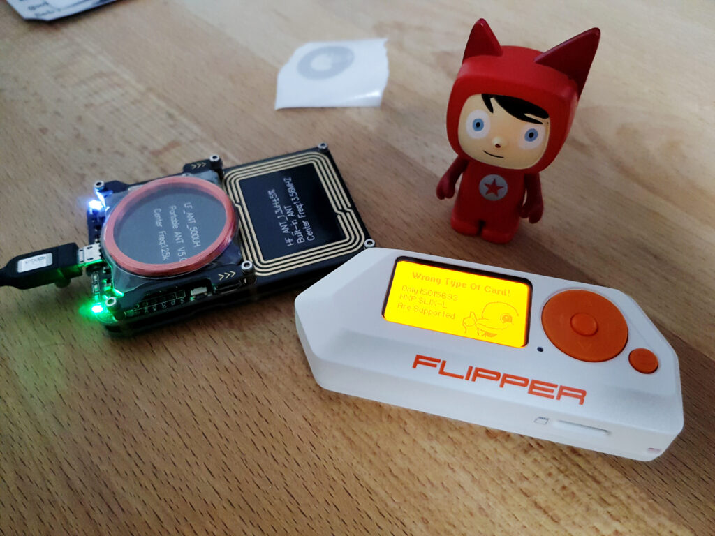
ISO15693 Block for AARONIA RTSA-Suite