Some time ago I built an aliexpress-part-based FPV quad and started flying around.
Well… A few days later I had to buy the same parts again. Due to winds I totally lost control and the drone went out of range just while I hit the throttle stick hard. It elevated beyond clouds and was gone and never to find again :)
Then I also bought a great remote control, the TBS Tango 2, a quite compact but feature rich remote for quads, so I can train flying skills in a simulator, before losing the next quad. While the Tango 2 is also capable of proper joystick emulation, it always felt a bit weird to have the cable connected, which is always a bit too short, no matter which length your USB-C cable has.
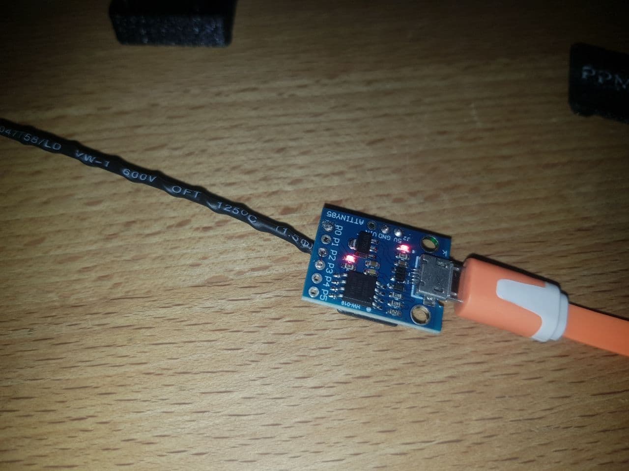
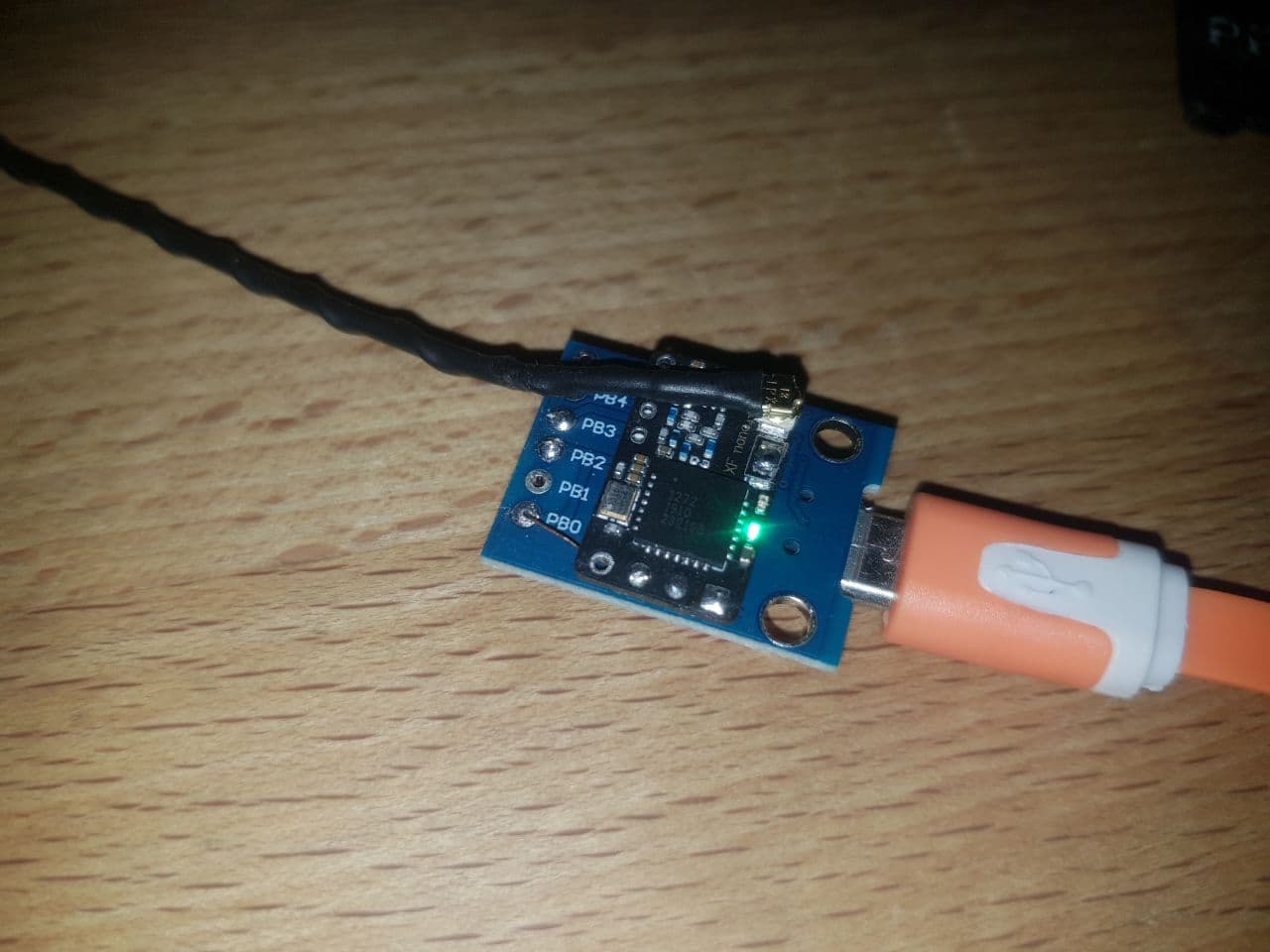
So I decided to pick a small DigiSpark with its neat ATtiny85 plus USB emulation and attach a Crossfire nano receiver and just implement that simple CRSF protocol and use the DigiSpark Joystick emulation example code.
Edit: If you want to know more about the inner workings of the protocol, see [FPV] Analysis of TBS Crossfire, reverse engineering the air link – g3gg0.de where I reverse engineered the air link protocol.
Yeah, wishful thinking.
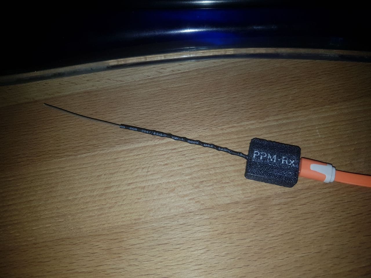
When I realized that the ATtiny85 has no hardware UART and software bitbanging looked unfeasible in parallel with USB bitbanging, I decided to do a first step using the PPM protocol. The Crossfire receiver allows to output this PWM-like protocol with all its downsides. Noise, latency and resolution are not as good as with crossfire.
Implementing PPM reading was not soooo hard, just a bit glitchy due to noise and USB interrupts inbetween. Those capture timers are also not the highes resolution you can have (i am used to Infineon TriCore Aurix and ARM) but hey, 8 bits resolution should be enough.
Right?
No. I could only use less than 7 bits of range due to the timer frequency. Either handle timer overflows and use a higher clock frequency or be happy with the 7 bits. Okay, another day gone, and realizing that the timer overflow interrupts delayed due to USB interrupts cause some dropouts of the signal, giving a really “unsteady flight feeling”. Small, barely noticeable but still present hickups in a linear movement plus the noise you always get when sampling PWMs.
To give USB interrupts a higher priority while allowing timer interrupts, I bridged PB2 and PB3 and reconfigured the USB interrupt to trigger on INT0 (external interrupt) instead of PCINT0 (pin change).
Still, I had a working PPM to USB adapter, for virtually any recent FPV quad Tx system.
I want more!
Nah, let’s focus our initial plan – interpreting the CRSF protocol with its 420 kBaud. We get into the field of playing with nops to get just the right timing. But I had the feeling it could work – I just have to make sure that the USB interrupt and the CRSF bitbanging are not interfering.
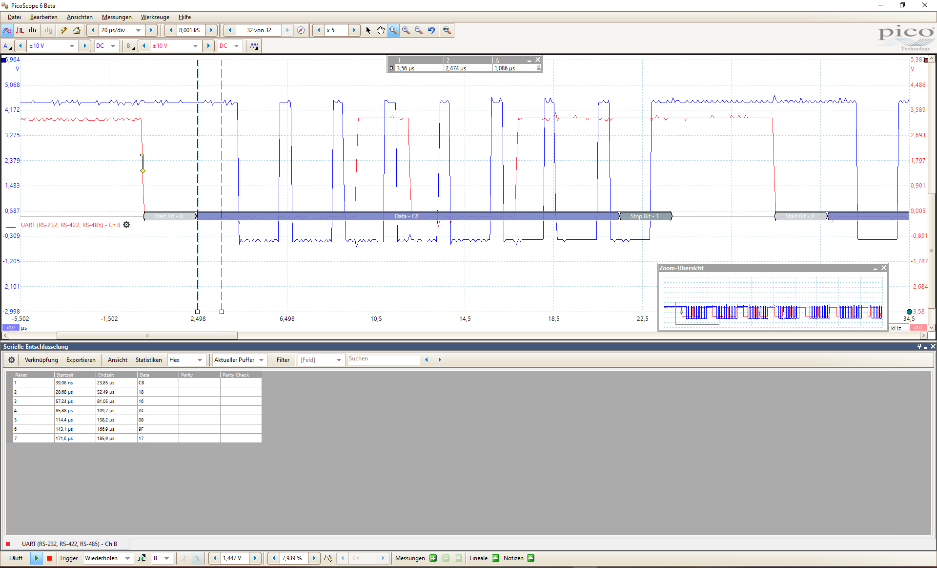
Using the LED pin (blue trace) and a scope I started to get just the right position where to sample the CRSF data line (red trace). If a CRSF packet is detected by its 0xC8 sync byte, I disable the USB interrupt for the duration of the packet, causing maybe one USB slot to be missed. But this seems fine from what I’ve seen.
One thing still riddles me: According to the ATtiny85 documentation, we only should have 4 cycles plus a few instructions latency and should end up with a microsecond. For some unclear reason the PCINT0 handler fires with a latency of about 2.5 microseconds and thus gets executed after start bit and just right for the first data bit.
But it works just fine, as we don’t need the start bit anyway.
Sticks and buttons
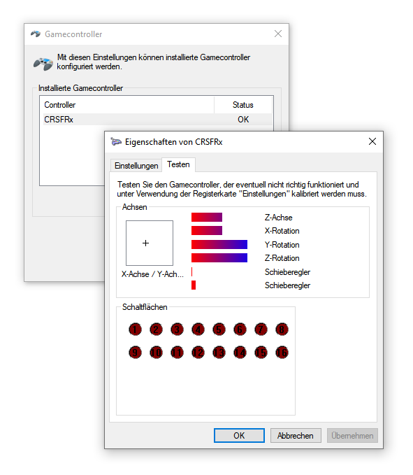
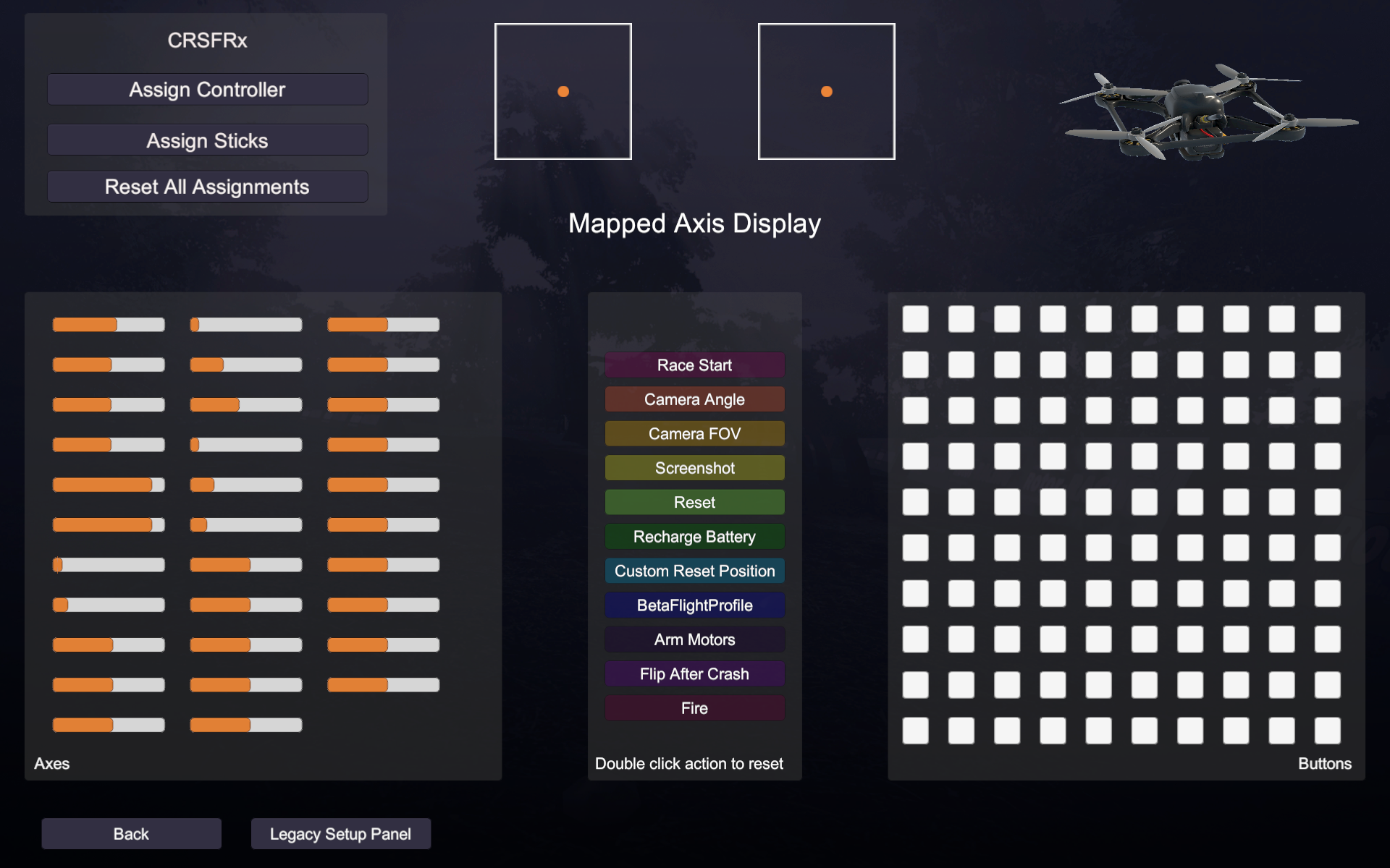
After also extending the DigiJoystick driver, the device properly sent 14 “analog stick” 8 bit values (CRSF channels 0 to 3, 10 and 11, a few rx link packet datas) plus 16 buttons. The buttons were calculated from the CRSF channels 4 to 9, giving a total of 12 used buttons and leaving 4 buttons free.
The button calculation is required as crossfire and other protocols sends button as “stick” values with a certain range, depending on the number of positions the button has. Currently there is only 3-way switches implemented, but that could be changed in the source. Alternatively I could simply pass all 12 channels through. Maybe I’ll change that.
The firmware
Download one of these files, remove the .txt extension and flash it using your Digispark uploader (micronucleus). The first file is passing channels 0-3 and the rest comes from link statistics, the second one routes all CRSF channels 0-11 through to the USB HID Joystick.
You can find the sources here: https://github.com/g3gg0/DigiJoystick_FPV
EDIT: the sources on github have some updates which make the USB connection more stable.
This is a library with two examples – a CRSF one and a PPM one Place it into your <Documents>\Arduino\libraries\ folder and use the provided examples.
Hint: PPM_Joystick may work or not – didn’t check it after refactoring for CRSF_Joystick.
Documentation is still missing, but I will update it in future. Maybe :)
Final thoughts
In the end it was a bit more lengthy than expected. CRSF with its high bitrate is not simple to implement along with USB, if you do not dig a bit deeper into timings and fine tune sampling points using nops. To be honest, my code is not really clean. Should have switched to assembler to a larger extent, but I am not used to atmel asm and wanted to get it working fast :)
Also the hardcoded USB HID descriptor lengths of V-USB did cost me time to find out why my device was often not enumerating. Wireshark for the win, I could at least find out that the last message was the HID descriptor and thus it had to be defective.
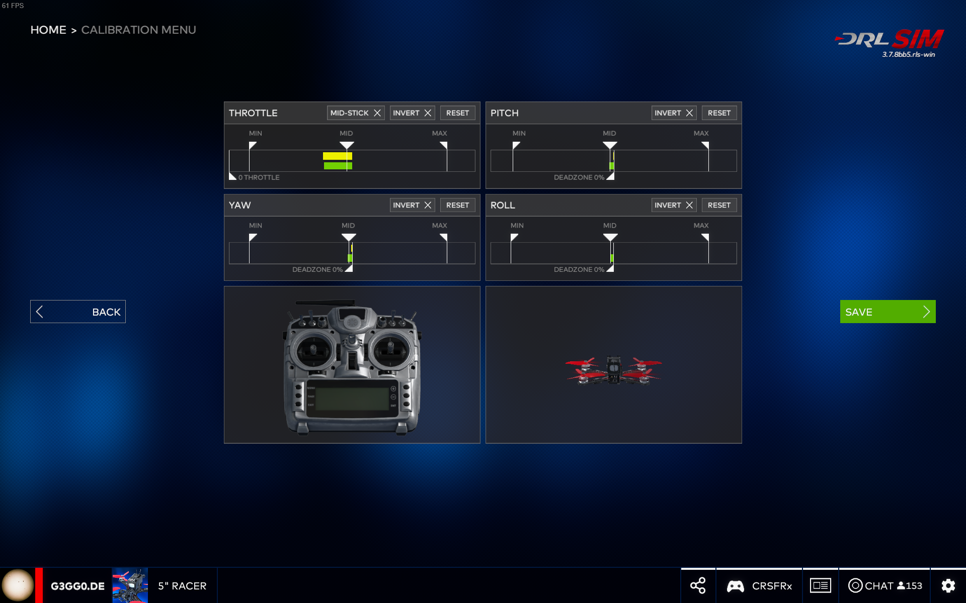
So i can now enjoy crossfire as it was meant to be: with a untethered remote and (sometimes) wearing the FPV goggles, feeding the VTX with the output of a 12€ HDMI->FBAS converter. Using this setup, I could even stand outside under the trees, flying a (virtual) drone in a more realistic environment.
Related Posts
Dyson v15 Battery Notes

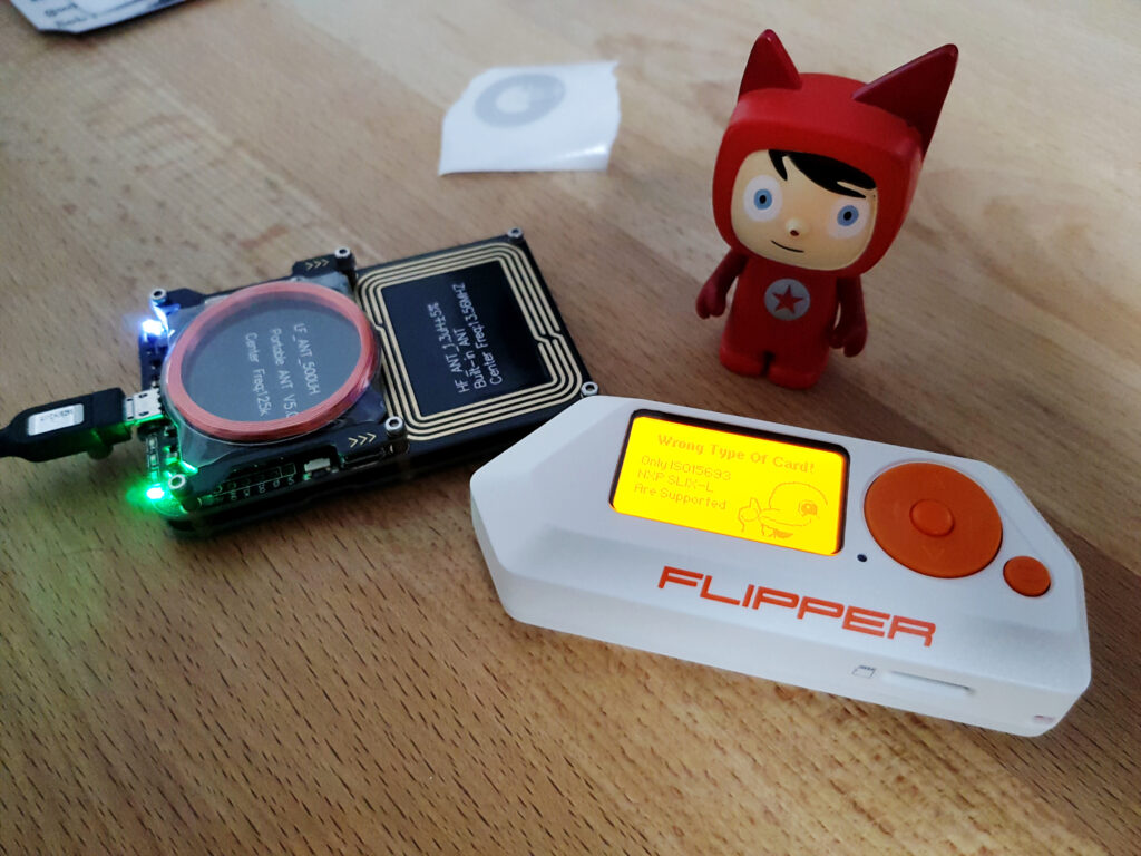
ISO15693 Block for AARONIA RTSA-Suite