[Update: 04/2018]
Summer ’16 I bought a prusa i3 clone from geeetech, a cheap chinese printer manufacturer.
With 270€, including VAT and shipping, the DIY-kit is quite cheap and 8 hours later i had a prusa i3 clone that prints “quite okay”.
[more about preventing your house burning down here]
This printer has a direct drive, bowdenless MK8-style extruder. While it prints really good, I wanted to have more flexibility.
So I started to design my own printhead with these constraints:
- exchangeable modules for: E3D v6 hotend, dual E3D v6 hotend, E3D Cyclops, plotter, laser cutter (more laserz, even more), …
- modules should be easy to change (no soldering, no screws, no levers)
- no rewiring when changing a module
- lightweight design
- easy to service
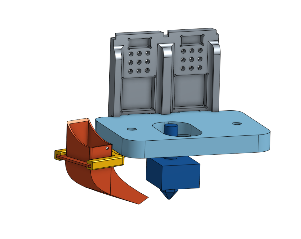
These lead me to a three-component setup, I designed in OnShape.
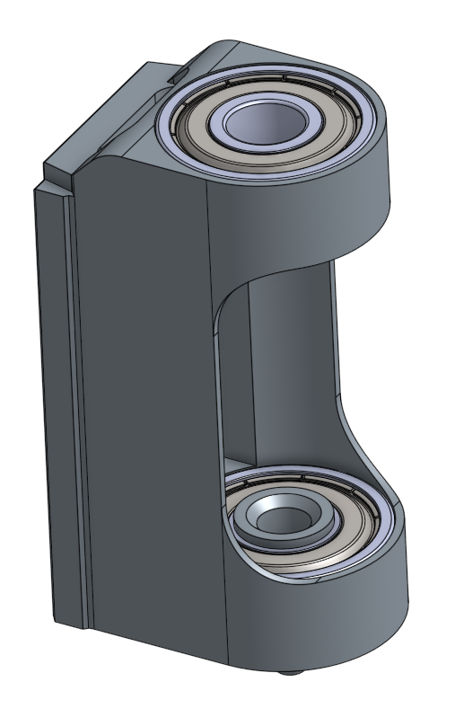
a) The X-Axis carrier.
Into this thing go all the screws. The SC8UU housings for the LM8UU linear bearings get mounted there, the belt attachment and the other printhead parts are mounted onto it.
The plate just connects the three ball bearings and provides a stable mount for the more complex baseplate with magnets, contacts and stuff.
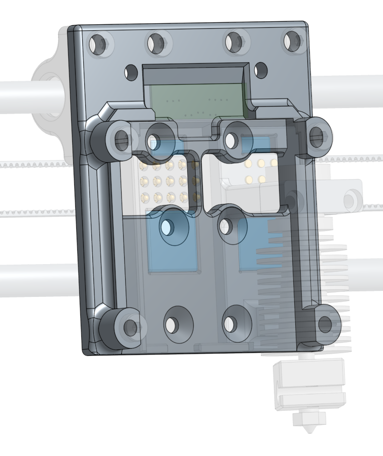
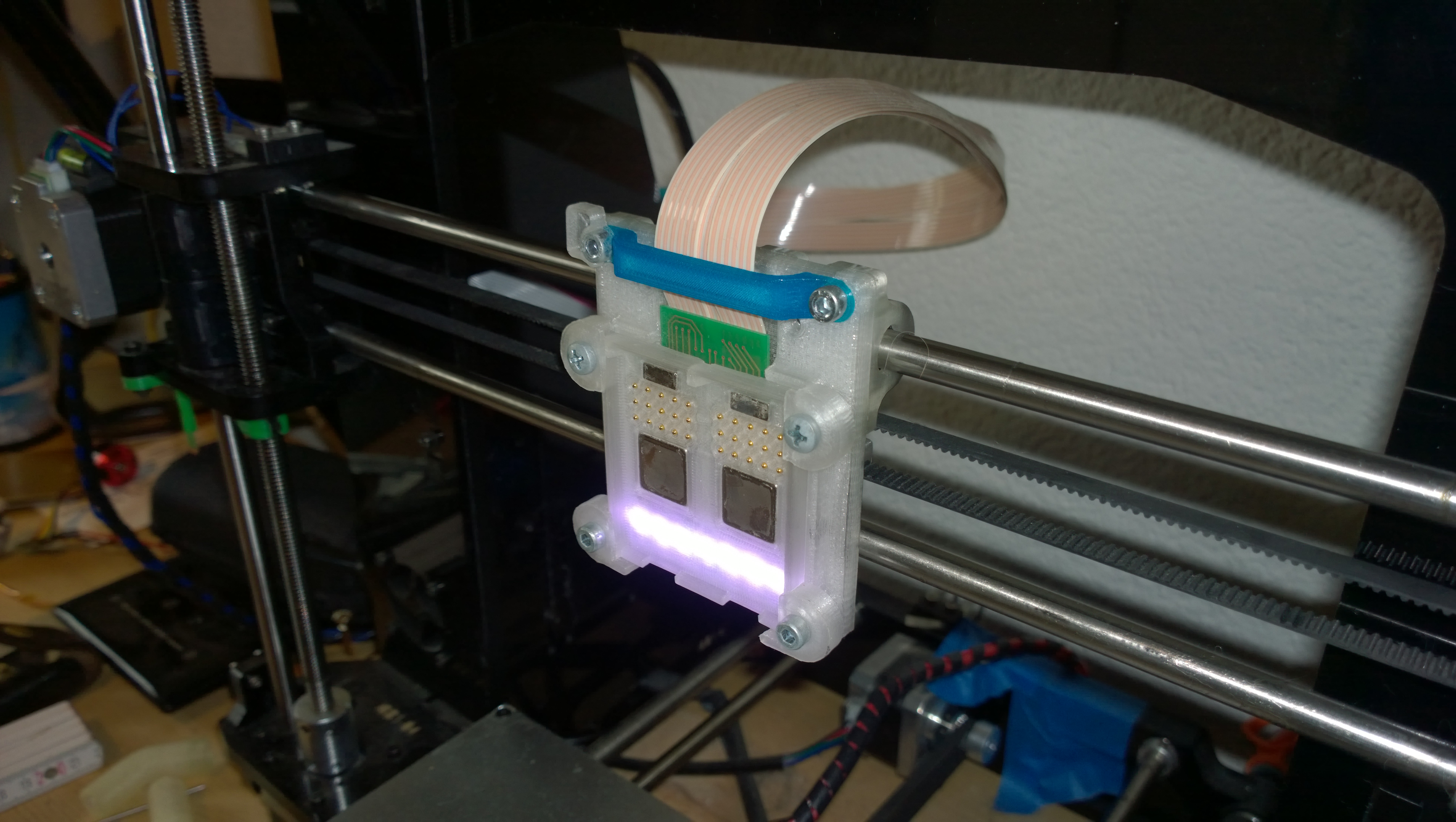
b) The thing, I call “Baseplate”
It is the electrical connector that holds the printhead in place with magnetic force.
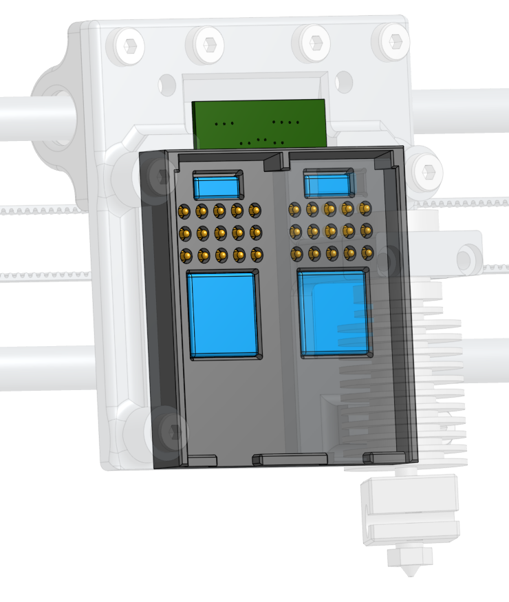
The Baseplate holds 30 pogo pins “GKS-967” from Ingun and each two “Q-10-04-02-N” and “Q-15-15-03-N” neodymium magnets from supermagnete.de.
While the magnets are quire cheap to get, the pogo pins and the counterparts were approx. 80€ , which is about 30% of the printer’s initial cost.
Not quite a el-cheapo design, but worth the money. Cost can for sure be reduced, but the first designs are not meant for this kind of experiments.
The layout of the connector is designed so printheads can be plugged in either of the two connectors, having the same pinout on both.
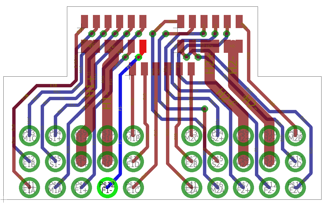
The pinout for every module has 9 “center” pins that are for the important lines – heater, thermistor and fan supply, where the high current traces and pogo pins are used in parallel.
The “outer” pins are for the (extruder) stepper motors and some spares for future use.
But there is a small caveat though – the fan pins are not equal. While one of them is PWM controlled, the other is always-on only. I can’t change this, as there is only one PWM capable output on the GT2560 mainboard.
Sure, could modify the board and add a MOSFET, but thats another story.
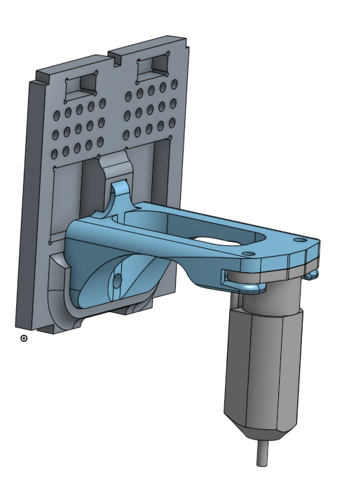
Also made a proper mount for the original MK8 extruder that gets snapped into the base plate.
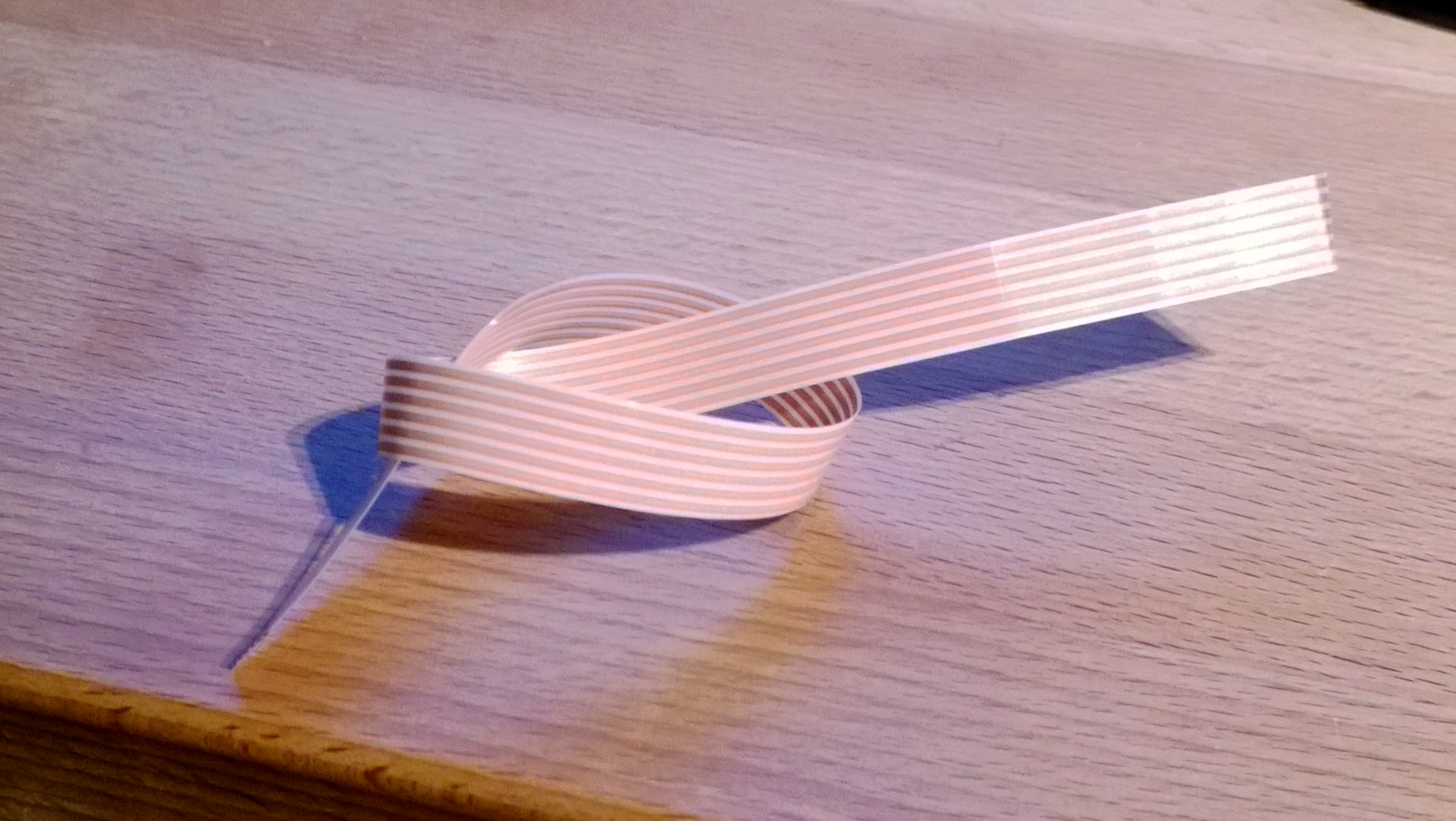
The pads you can see in the upper part of the PCB are the solder pads for the flexband I harvested from Audi/Volkswagen steering angle sensors.
One of the next steps is to use five flexbands and solder them onto the PCBs. I have the same PCB twice, one in the baseplate and one next to the printer’s main PCB.
c) The printhead modules
The print heads are designed for various purposes, mainly for FFF print heads, but also some other tools.
Meanwhile I designed various print heads, some are listed here:
Here a video of the current status, feels quite stable thanks to dasfilament PETG which I can absolutely recommend.
This video shows how well the printheads snap into the base plate. The four neodymium magnets leave no play and deliver a solid mechanical feeling.
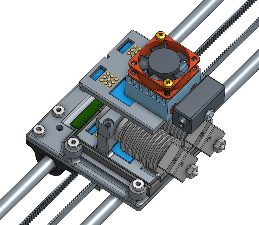
Here photos of the printhead with flex bands attached
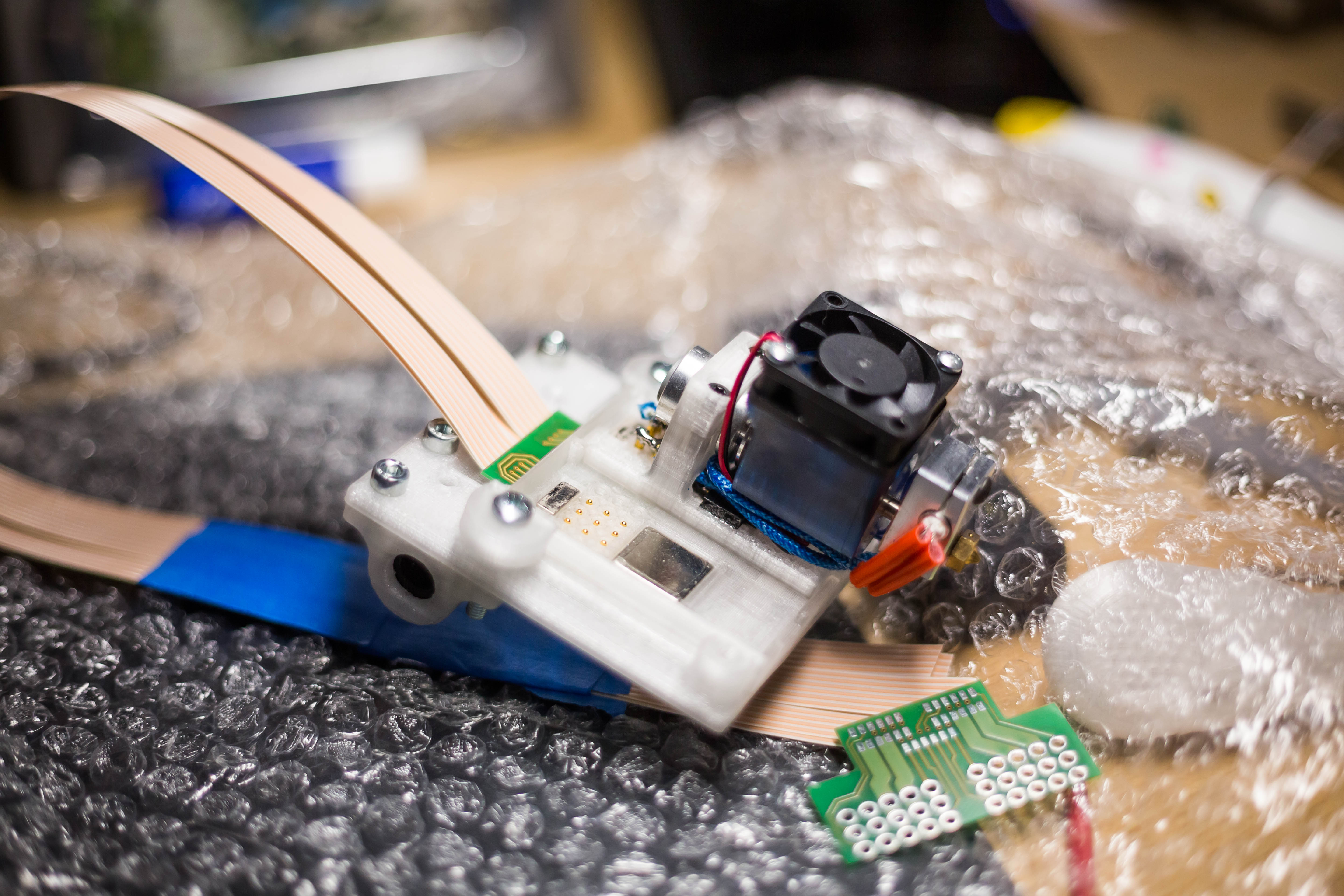
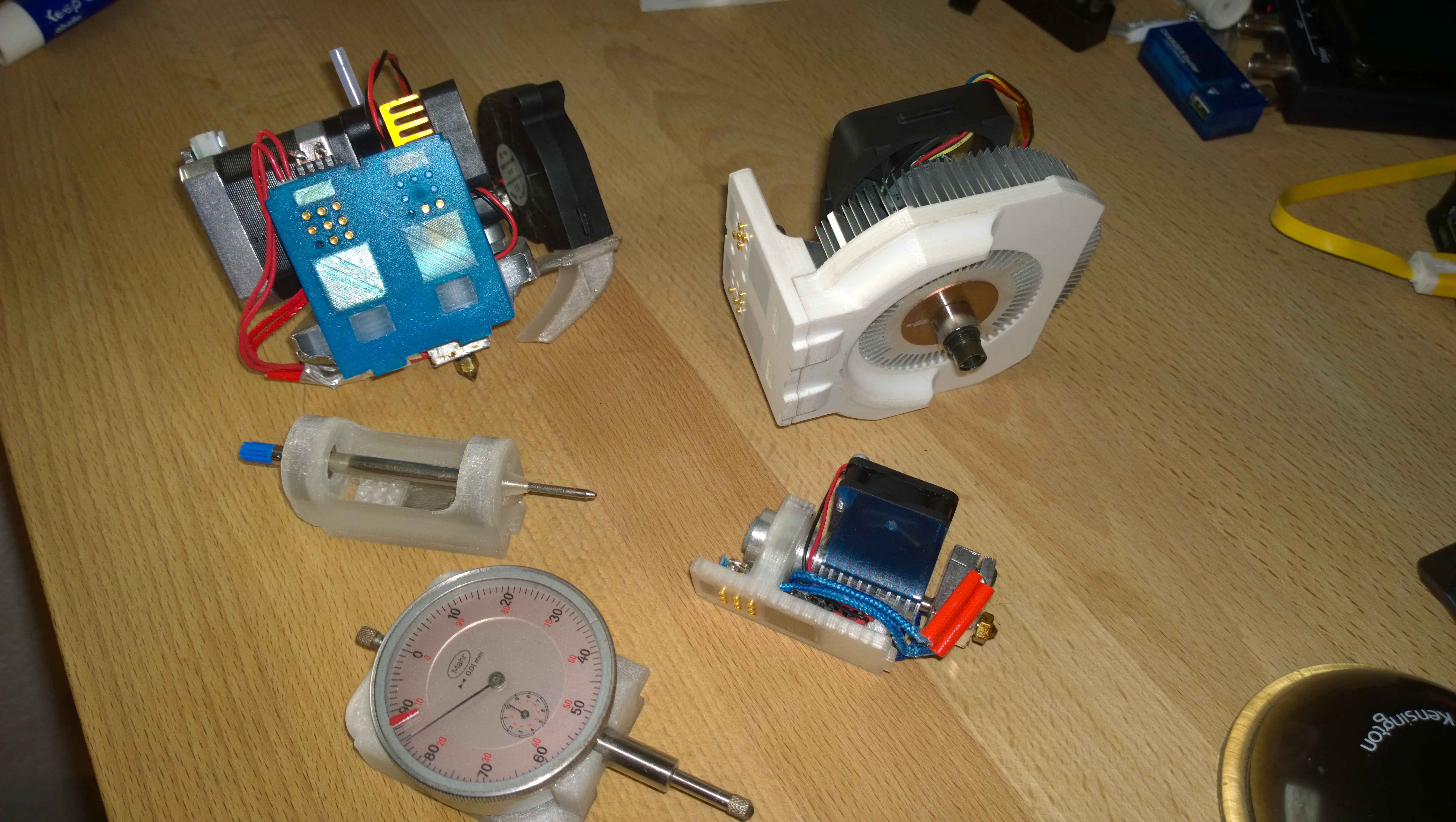
This photo shows some of my printheads in real hardware:
1. MK8 Extruder
2. Laser 450nm, 1.6W
3. ball pen plotter head
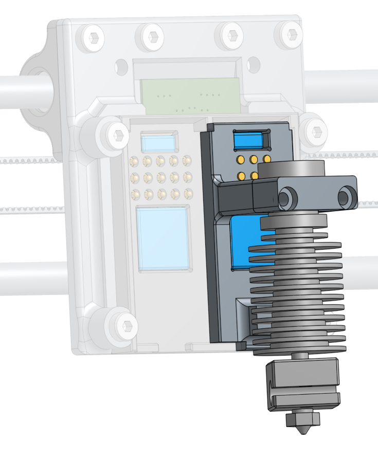
4. E3D v6 hotend for bowden
5. micrometer dial indicator
After more than a year of use, I am so statisfied with the result. Swapping from the Mk8 extruder to the laser head within 5 seconds and then lasering a piece of wood with ease makes this piece of hardware much more usable.
So my printer is not only for squeezing hot plastic through a brass nozzle anymore, but also for engraving wood using a mill.
Sure, milling with that acrylic frame and wobbly axis will not give the best results (not to speak about the dust this hardware isn’t designed for), but are at least a funny experiment.
The best decision was to use the flex cable, which is not easy to get unfortunately. It really is a good feeling when you don’t have to fear broken cables.
No need for a drag chain, no sloppy cables, helping to reduce the risk of serious fail that could burn your house down.