A friend handed me a dead Dyson battery, and I took a look just out of curiosity.
That’s how most of my “14 days of staying up until 3 AM” adventures usually start.
Not this time – this is just me documenting a few findings I haven’t seen online yet.
The main processor appears to be an ATSAMD20E15, paired with a BQ7693003 battery monitor chip. I didn’t dig much deeper into the circuitry; others have already done solid writeups on older Dyson battery packs.
The short version: there’s no active balancing. Once a cell drifts by around 300 mV, the microcontroller shuts everything down and blocks both charging and discharging. At that point, the pack is effectively bricked. One cell drifting isn’t rare – that’s why balancing circuits exist. This model doesn’t use a monitor chip with balancing support, while earlier models did but simply left the balancing resistors unpopulated. Adding them would’ve cost only a few cents, plus a bit more thought on thermal design.
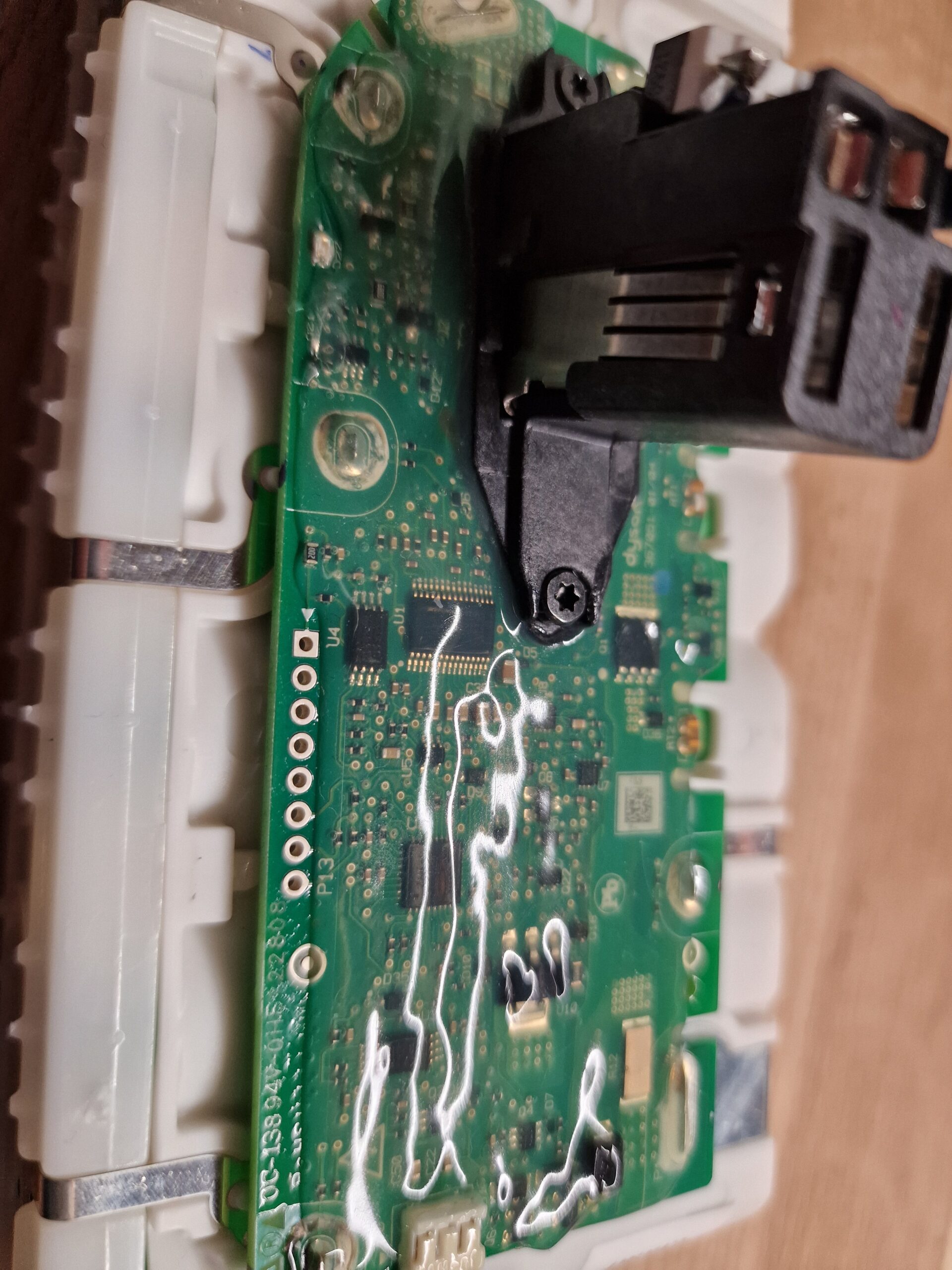
Looking closer, I quickly found the debug/programming header and mapped the pinout. Pressing the lever on top of the connector closes a switch and powers the microcontroller with 3.3 V. Pin 1 jumps to that VCC level, pin 2 is GND. Releasing keeps the uC powered for a few seconds.
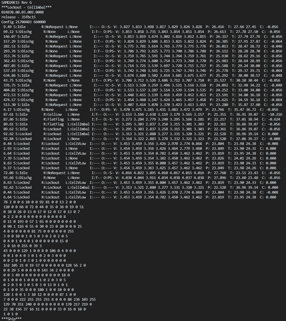
Probing pin 3 immediately revealed a 115.2 kBaud UART stream telling me why the pack acted dead:
***Lockout – CellImbal***
At least it’s verbose, logging all cell voltages and matching my multimeter readings.
Even after bringing the low cell back up, the microcontroller shows zero mercy and keeps the pack locked down.
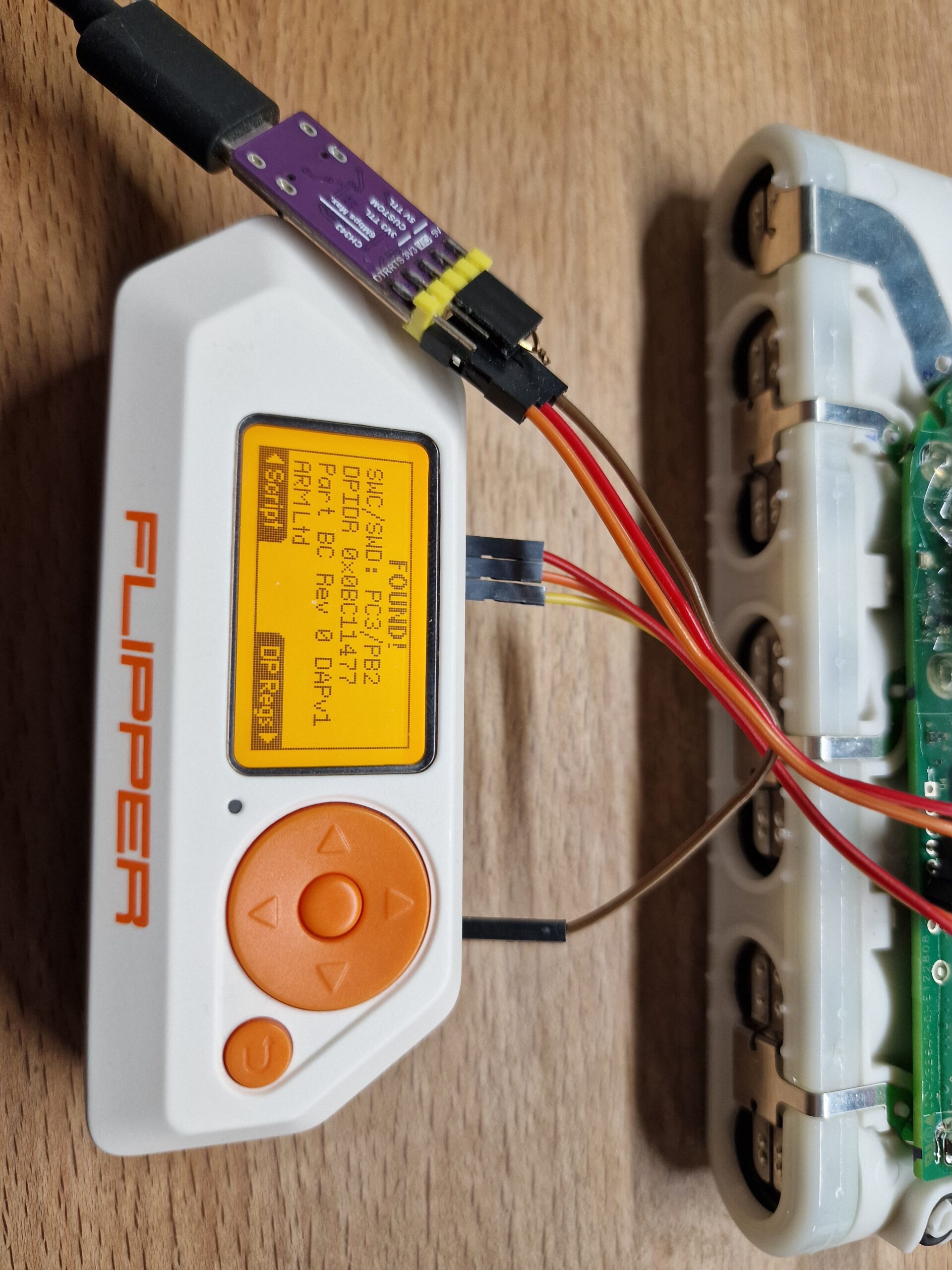
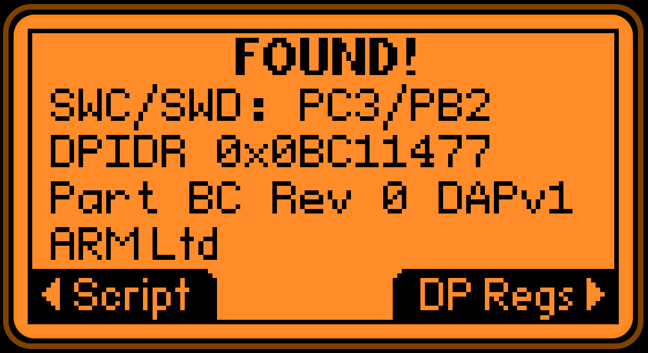
After further probing with my flipper and the SWD-Probe app, I confirmed the SWD pins as well.
So the final pinout is:
1 – VCC – 3.3V
2 – GND
3 – PA10 – TX (115.2k)
4 – PA11 – RX (unconfirmed)
5 – PA00 – has effect on blue LED
6 – PA30 – SWC (100k pup)
7 – PA31 – SWD (100k pup)
8 – RST (10k pup)
The last three pins have some obvious pull ups. Didn´t measure for the other pins yet.
PA05 – BQ SDA
PA17 – BQ SCL
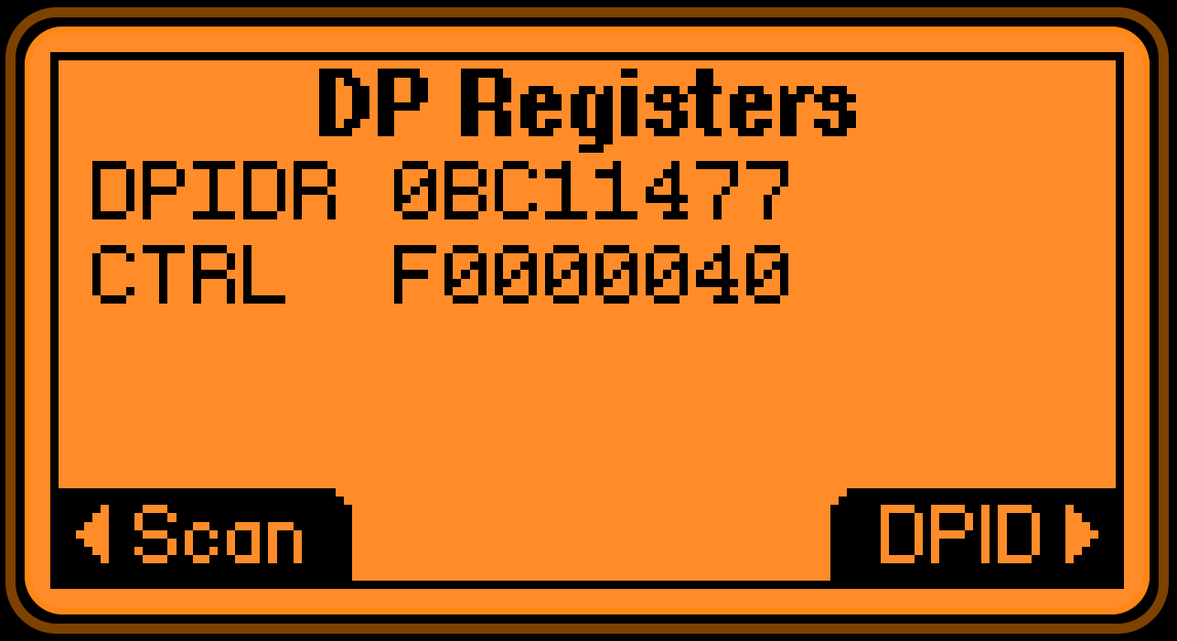
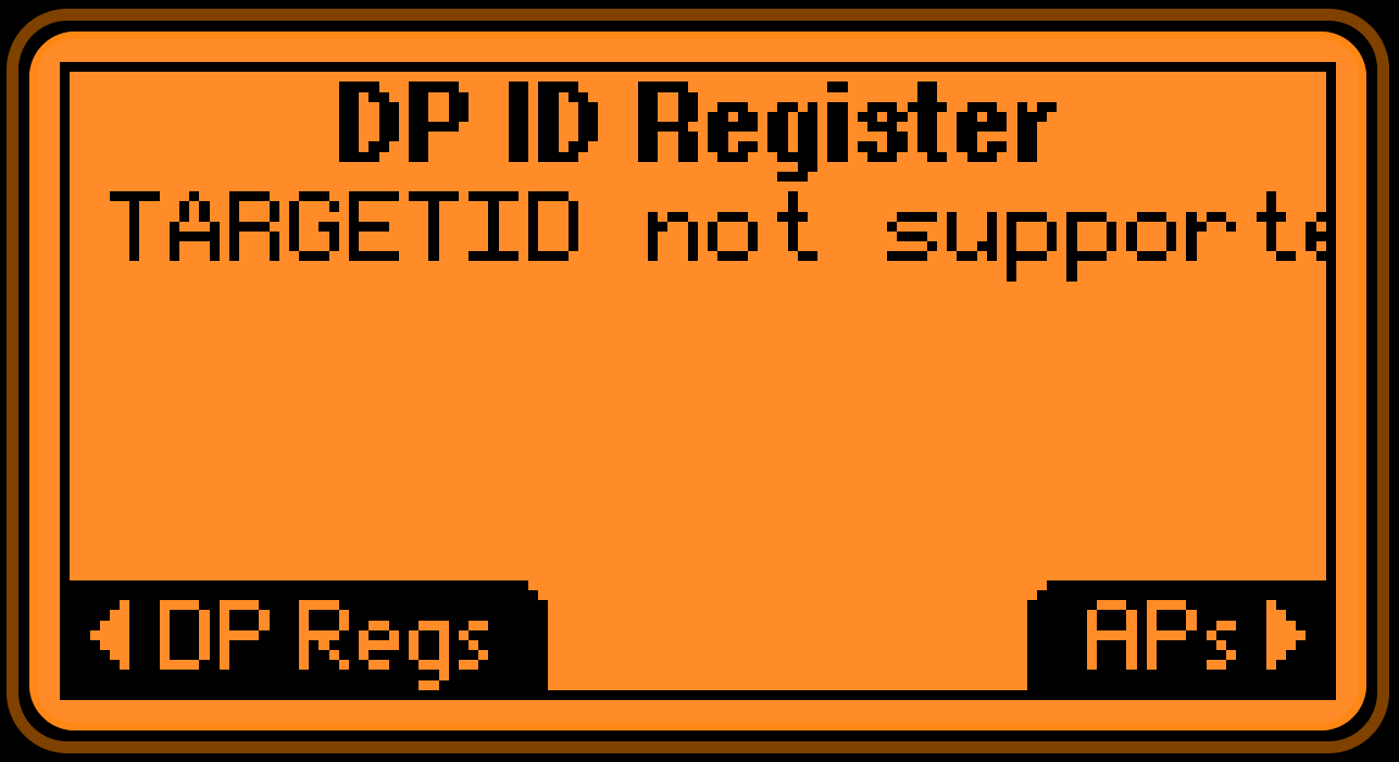
Getting the SWD-Probe app to identify the chip is much more than I expected. I genuinely thought, the JTAG circuitry is locked down, but reading from the memory bus doesn´t work either. So maybe it´s locked down – or – my SWD-Probe app needs some tweaking with SWD registers before. Wouldn´t be the first time, using a Lauterbach debugger worked like a charm.
Maybe I will try this somwhen.
Edit: tried with Lauterbach PowerDebug and could not get further than reading some chip ids.
Update:
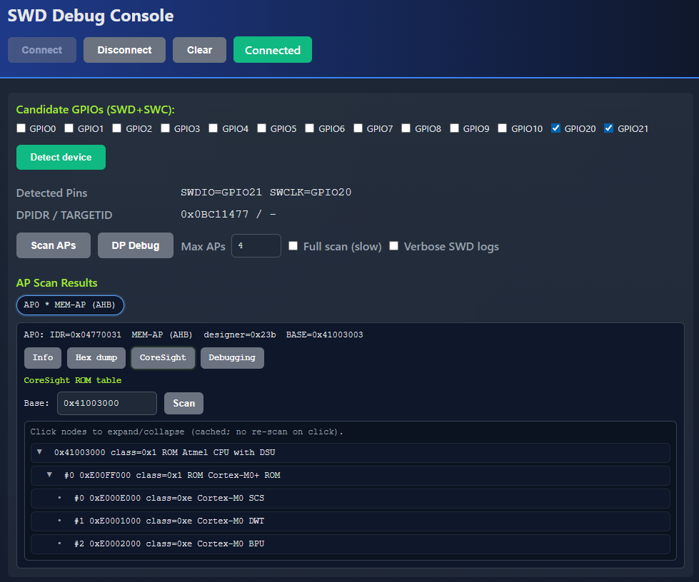
As I recently worked on using an ESP32-C3 as a USB UART replacement, I also experimented with SWD from browser. More details will follow.
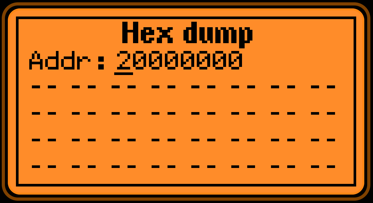
But I digged deeper into the DSU of the ATSAMD and accidentially set the bit for chip erase. Before that, I tried to calc the checksum of the flash area using the DSU and that seemed to work.
Unfortunately due to a off-by-one error, I set the chip erase bit and now the flash is empty.
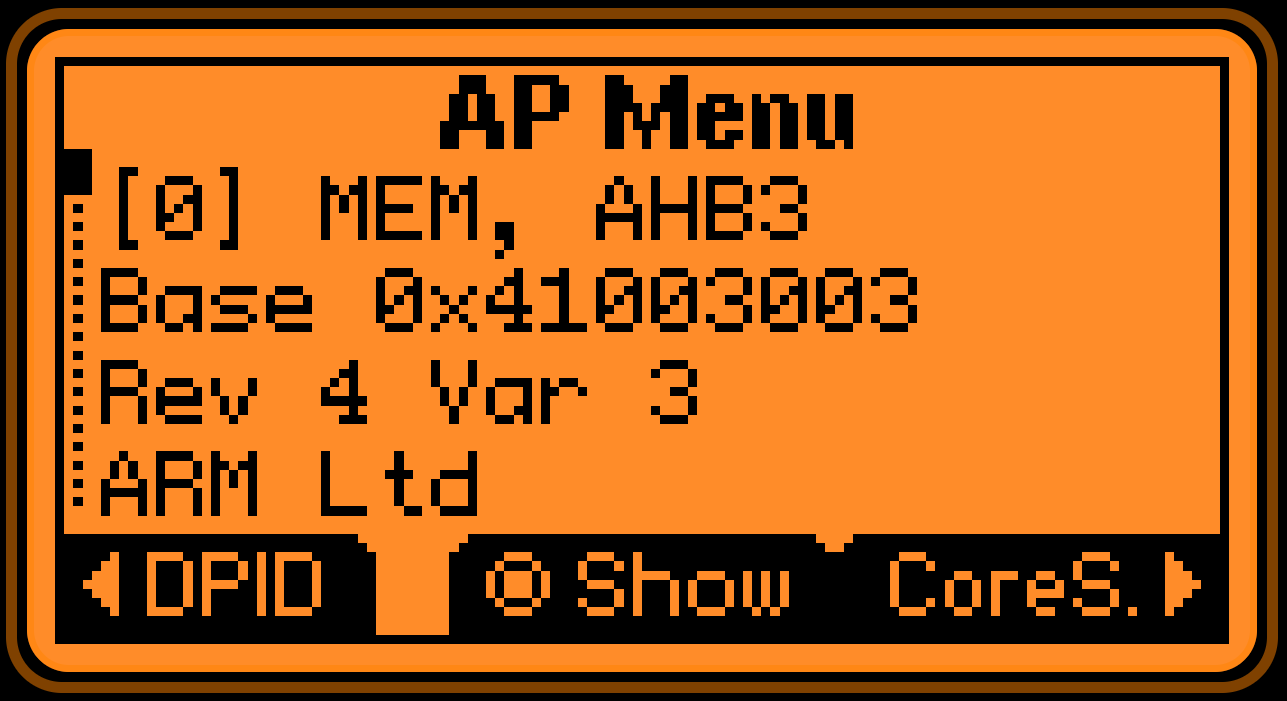
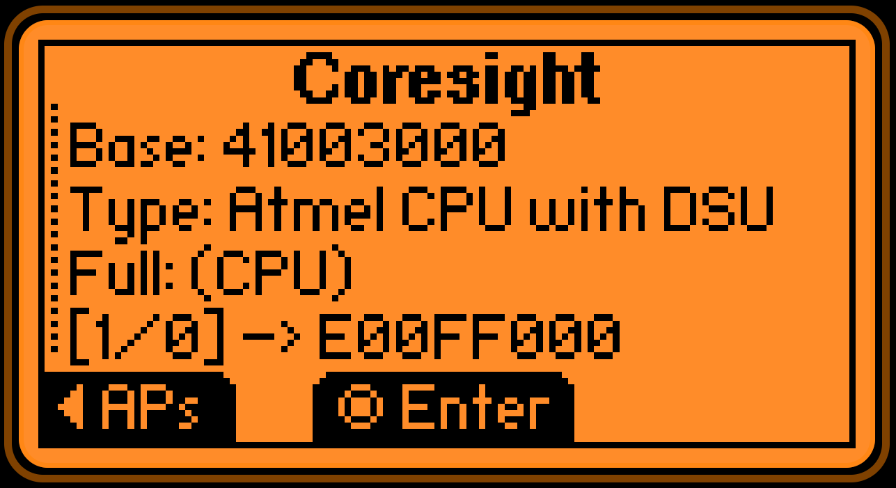
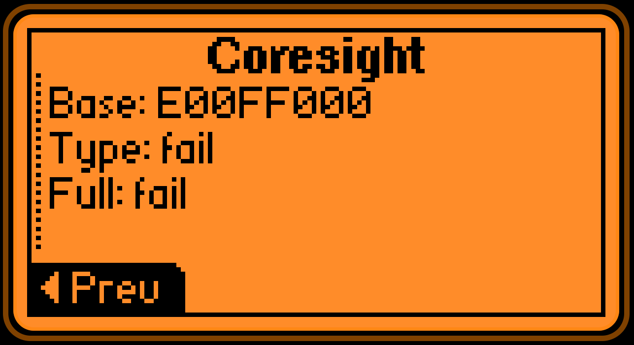
The good thing is, that I can now see the full CoreSight table including SCS.
Which is a proof that the PROT bits were definitely set before.
Related Posts
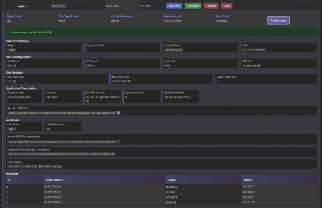
[ESP32] Browser-based firmware image viewer and editor
Flipper Zero got ISO15693 (NFC-V) support